

Multiphase current supplying circuit, driving apparatus, compressor and air conditioner
a multi-phase current supply circuit and circuit technology, applied in the direction of dynamo-electric converter control, motor/generator/converter stopper, dynamo-electric gear control, etc., can solve problems such as peak value, and achieve the effect of significantly reducing the capacitance of capacitors in the intervening circui
- Summary
- Abstract
- Description
- Claims
- Application Information
AI Technical Summary
Benefits of technology
Problems solved by technology
Method used
Image

Examples
first embodiment
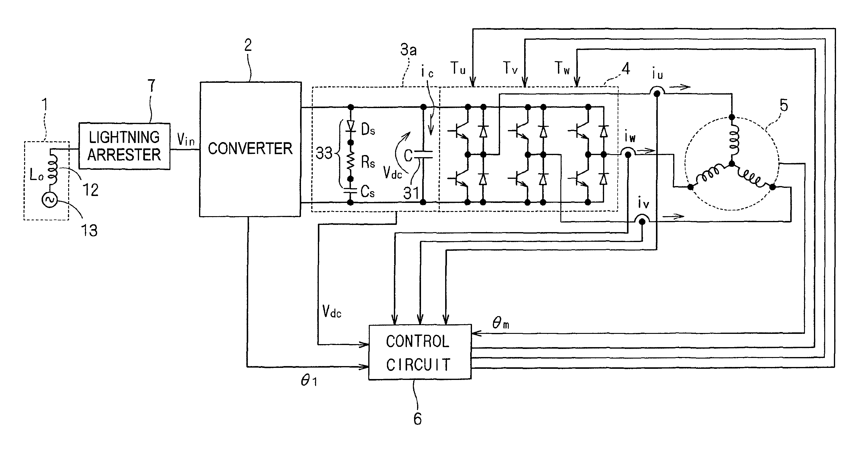
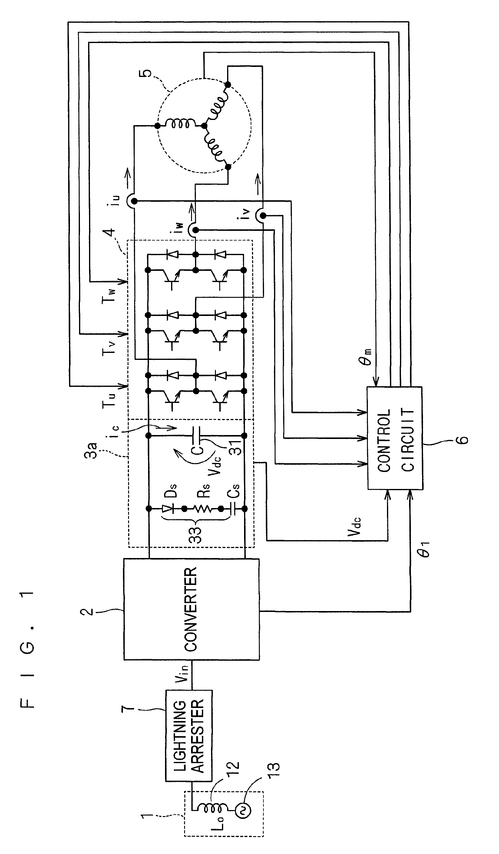
[0058]FIG. 1 is a circuit diagram showing a driving apparatus according to the first embodiment of this invention. The driving apparatus is provided with a motor 5 serving as a driving part and a multiphase current supplying circuit for supplying multiphase currents thereto.
[0059]The multiphase current supplying circuit includes a converter 2, an intervening circuit 3a, an inverter 4, a control circuit 6 and a lightning arrester 7. A single-phase or a multiphase, e.g., three-phase power supply system 1 is connected to the converter 2 with the lightning arrester 7 interposed therebetween, and the ac voltage Vin is rectified. Since a parasitic inductance exists in the power supply system 1 as described above, the parasitic inductance is shown as an inductor 12 connected in series to an ac power supply 13. A value of 230 μH was employed as the parasitic capacitance L0 of each phase.
[0060]The converter 2 rectifies the ac voltage Vin and inputs it to the intervening circuit 3a. The inter...
second embodiment
[0088]FIG. 8 is a circuit diagram showing an intervening circuit 3b employed in a driving apparatus according to a second embodiment of this invention. The intervening circuit 3b is configured with an inductor 32 further added to the intervening circuit 3a. Specifically, the inductor 32 is connected in series to the parallel connection of the capacitor 31 and bypass 33. Employing the intervening circuit 3b as the intervening circuit 3 shown in FIG. 1 not only allows the bypass 33 to exert its function, but also decreases the rising angle of current flown into the parallel connection of the capacitor 31 and bypass 33 by the inductor 32. This can suppress with more efficiency the voltage rise in the rectified voltage Vdc when a lightning surge occurs.
[0089]FIG. 9 is a graph showing the waveform 101 of the ac voltage Vin, a waveform 105 of the both-end voltage of the capacitor Cs, and a waveform 106 of the rectified voltage Vdc. The values having been described so far were employed as ...
third embodiment
[0093]FIG. 10 is a circuit diagram showing part of a multiphase current supplying circuit according to a third embodiment of this invention. The converter 2, inverter 4 and lightning arrester 7 are omitted, but are configured similarly to FIG. 1. In this embodiment, an intervening circuit 3d is employed in place of the intervening circuit 3a shown in FIG. 1.
[0094]The intervening circuit 3d is configured with a bypass 34 added in parallel to the capacitor 31 in the intervening circuit 3a described in the first embodiment using FIG. 1. The bypass 34 has a series connection of a transistor Q serving as a switching device and a resistor RB.
[0095]The control circuit 6 supplies a bias voltage CNQ to the base of the transistor Q on the basis of the rectified voltage Vdc. When the rectified voltage Vdc exceeds a first predetermined value, the transistor Q turns on, and when the rectified voltage Vdc falls below a second predetermined value (this is lower than the first predetermined value),...
PUM
 Abstract
Description
Claims
Application Information