
Instruments for measuring nanoparticle exposure

a technology of instruments and nanoparticles, applied in the direction of instruments, material analysis using wave/particle radiation, separation processes, etc., can solve the problems of increased losses, difficult mass concentration measurements, and lack of requisite sensitivity

Active Publication Date: 2010-10-12
TSI INC
View PDF12 Cites 13 Cited by
  • Summary
  • Abstract
  • Description
  • Claims
  • Application Information

AI Technical Summary

Benefits of technology

The present invention provides a measurement instrument that can more accurately measure the deposition of nanoparticles in the respiratory system, particularly in the tracheobronchial region, alveolar region, and naso-pharyngeal region. The instrument can selectively adjust the results to match a predetermined function describing the behavior of aerosol particles. The invention also includes an ion extraction device that can selectively remove excess ions and other higher mobility elements from the aerosol stream, and a system tuning component that can adjust the operating parameters of the instrument to better match the behavior of the particles. The invention also includes a process for extracting ions and charged particles from an aerosol stream and a device for selectively modifying the distribution of charged particles in the aerosol stream. These technical effects can be used to non-invasively assess nanoparticle exposure and provide a more accurate measure of the health effects of nanoparticle deposition in the respiratory system.

Problems solved by technology

These developments have raised concerns, because the occupational health risks associated with manufacturing and using nanomaterials are not clearly understood.
Moreover, due to the small mass of nanoparticles, mass concentration measurements are difficult to obtain and lack the requisite sensitivity, even when based on particle accumulation such as through collection of particles on a filter.
Particle measurements based on number concentrations are more sensitive, but subject to increased losses and reduced counting efficiency in the nanometer size range.
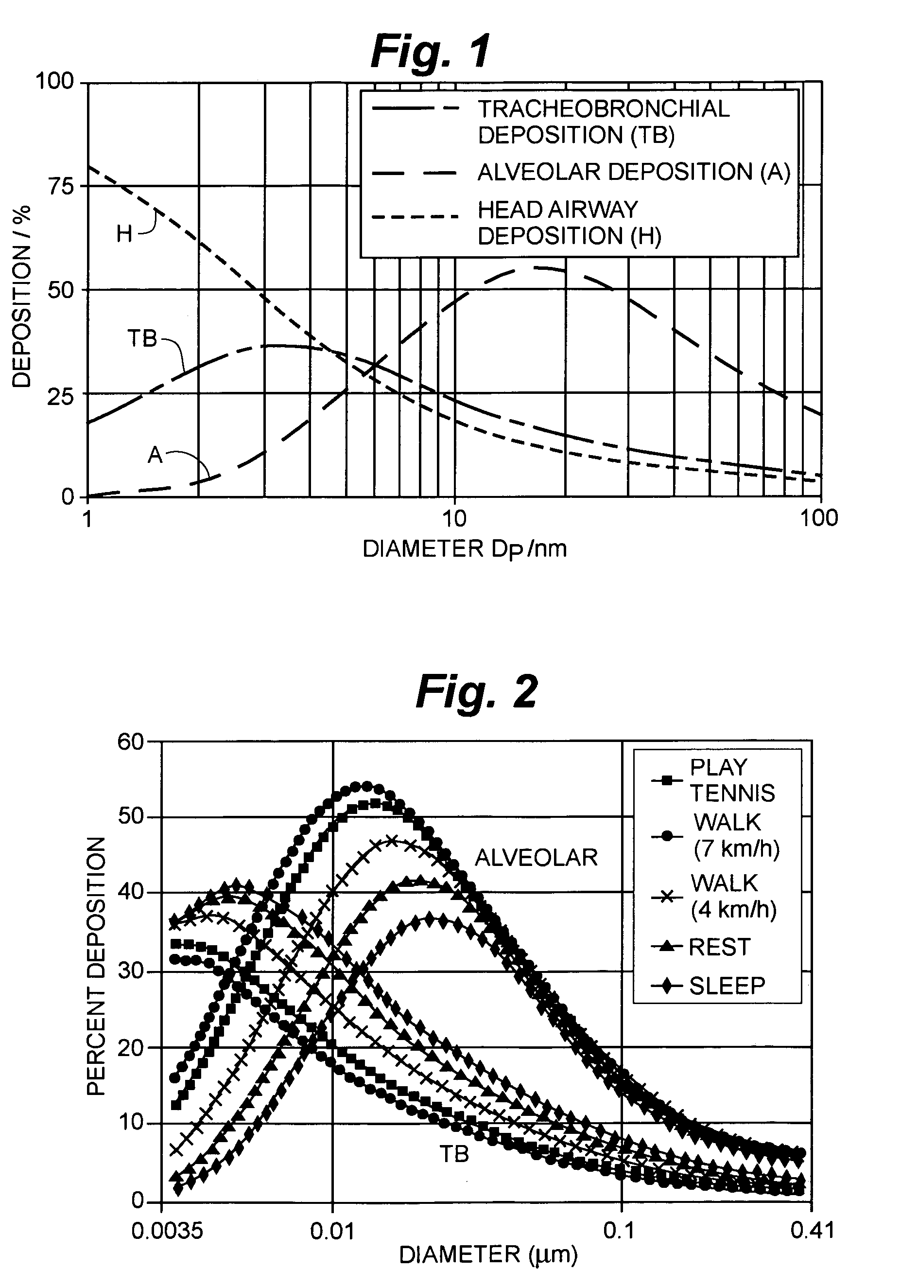
Deposition in the head (naso-pharyngeal) region raises a risk of particles reaching the brain.
However, particles deposited in the alveolar region are more likely to be transferred to the blood, and less likely to be expelled, because of a less efficient clearing mechanism.

Method used


Image

  • Instruments for measuring nanoparticle exposure
  • Instruments for measuring nanoparticle exposure
  • Instruments for measuring nanoparticle exposure

Examples


Embodiment Construction

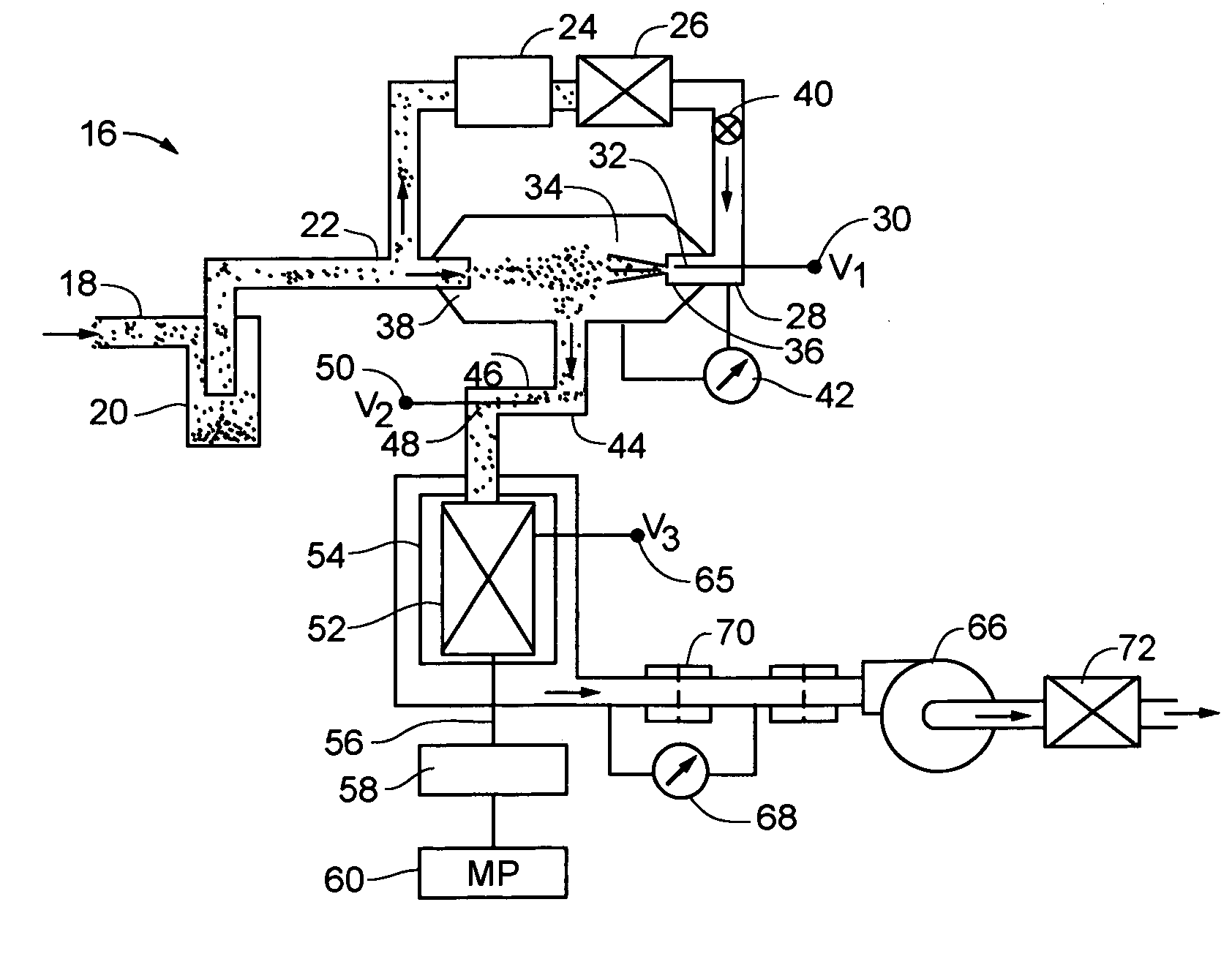
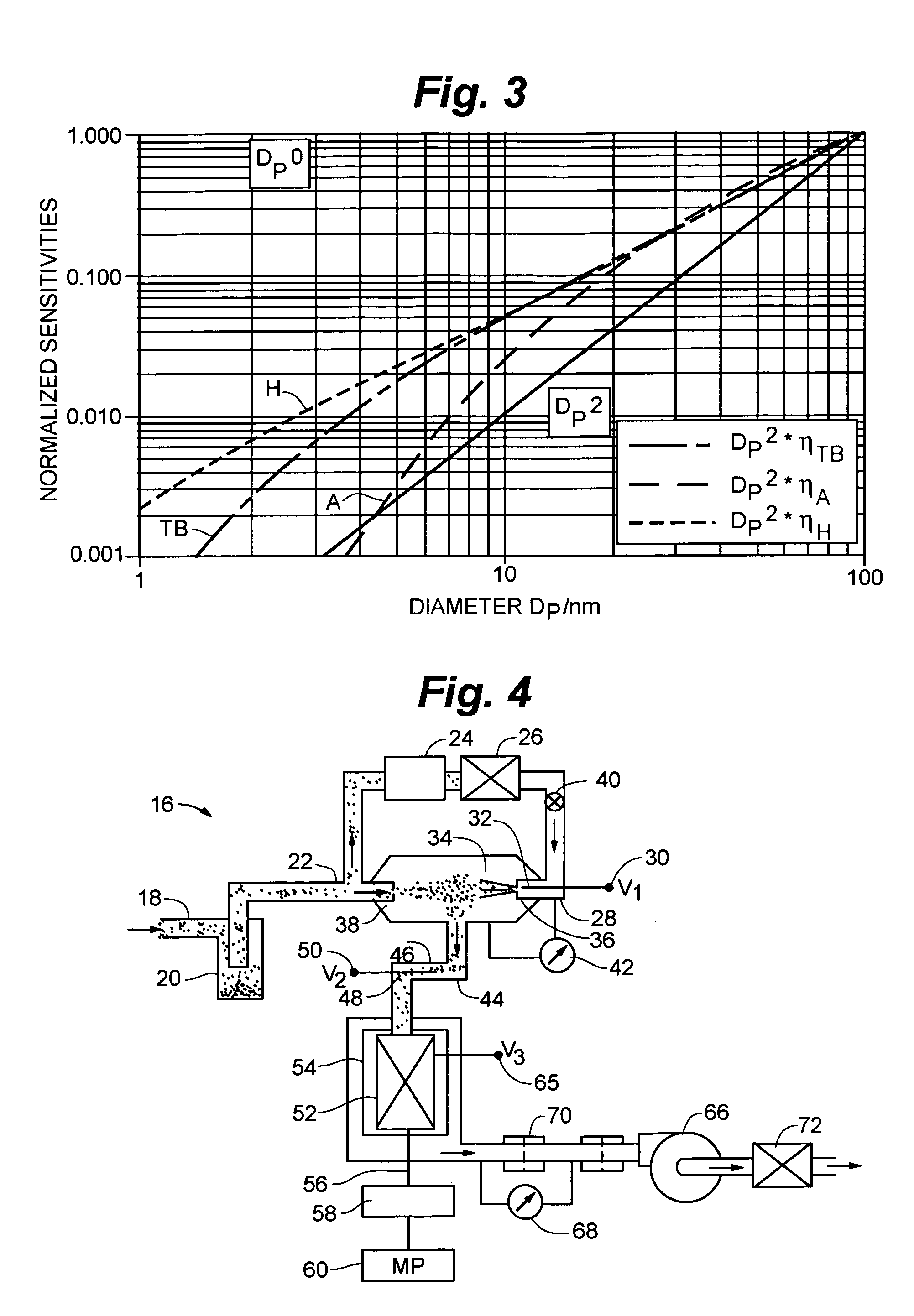
[0056]Turning now to the drawings, there is shown in FIG. 4 an aerosol particle sampling instrument or device 16. Device 16 is configured to facilitate adjustments to simulate particle deposition in the lung or elsewhere in the respiratory system. An aerosol is received at an inlet conduit 18 and directed through a large-particle separator such as a cyclone 20, to remove particles having aerodynamic diameters that exceed one micron. Flowing at 2.5 lpm, the aerosol reaches a junction 22 where a 1.0 lpm auxiliary flow is diverted through an activated carbon filter 24 and a high efficiency particle air (HEPA) filter 26 to provide a clean air stream. Downstream of filters 24 and 26 is a corona discharge needle 28, which is biased to a high positive voltage e.g. two kilovolts) V1 from a terminal 30. As a result, needle 28 generates positive ions at its tip 32. The clean air stream entrains the ions, conducting them away from tip 32 and into a mixing chamber 34 through an orifice 36.

[0057...


PUM


Abstract

An instrument for non-invasively measuring nanoparticle exposure includes a corona discharge element generating ions to effect unipolar diffusion charging of an aerosol, followed by an ion trap for removing excess ions and a portion of the charged particles with electrical mobilities above a threshold. Downstream, an electrically conductive HEPA filter or other collecting element accumulates the charged particles and provides the resultant current to an electrometer amplifier. The instrument is tunable to alter the electrometer amplifier output toward closer correspondence with a selected function describing particle behavior, e.g. nanoparticle deposition in a selected region of the respiratory system. Tuning entails adjusting voltages applied to one or more of the ion trap, the corona discharge element and the collecting element. Alternatively, tuning involves adjusting the aerosol flow rate, either directly or in comparison to the flow rate of a gas conducting the ions toward merger with the aerosol.

Description

[0001]This application claims the benefit of priority of: Provisional Application No. 60 / 683,615 filed May 23, 2005; and Provisional Application No. 60 / 763,555 filed Jan. 31, 2006.BACKGROUND OF THE INVENTION[0002]The present invention relates to systems and devices for measuring concentrations of nanometer or ultrafine particles, and more particularly to such systems that are adjustable in terms of their sensitivities to certain sizes or electrical mobilities of particles or sets of particles within the nanometer range.[0003]When materials are produced or formed in the nanometer size range, i.e. from about 0.1 micrometers in diameter down to molecular levels, they exhibit unique properties that influence their physical, chemical and biological behavior. Nanotechnology, the field of endeavor concerned with materials in this size range, has experienced explosive growth over the last several years as new and diverse uses for nanomaterials are discovered and developed throughout a broad...

Claims


Application Information

Patent Timeline
Patent Type & Authority Patents(United States)
IPC IPC(8): H01J49/00
CPCG01N23/00G01N27/622G01N15/0266G01N2015/0038B03C3/017B03C3/09B03C3/12B03C3/38B03C3/41B03C3/47
Inventor FISSAN, HEINZTRAMPE, ANDREASPUI, DAVID Y. H.KAUFMAN, STANLEY L.
Owner TSI INC
Learn More