Direct electric resistance liquid heater

a liquid heater and direct electric technology, applied in the direction of fluid heaters, water heaters, lighting and heating apparatus, etc., can solve the problems of shortened life, element failure, system meltdown, etc., and achieve the effect of virtually eliminating corrosion problems

Active Publication Date: 2010-10-19
OHMIQ INC
View PDF18 Cites 48 Cited by
  • Summary
  • Abstract
  • Description
  • Claims
  • Application Information

AI Technical Summary

Benefits of technology

[0013]In the present invention these and other difficulties, as will become apparent, are overcome in a direct electrical resistance liquid heater having many unique and previously undisclosed aspects. In one aspect, the invention comprises a liquid heating chamber with a liquid inlet and a liquid outlet in which a plurality of thin, spaced apart electrodes comprise an electrode array, the electrodes defining a plurality of channels, the spaces between the electrodes, through each of which liquid flows from the inlet to the outlet, and in which the liquid is heated when a voltage is connected between one or more pairs of electrodes. The use of thin electrodes avoids the creation of significant amounts of latent heat thus helping to minimize the potential response time to liquid flow rate or conductivity changes.
[0018]In a sixth aspect of the invention, an adequate number of current levels are defined, over a full range of liquid conductivities, to enable good operation of a temperature control loop and to provide current control such that a preset maximum current is not exceeded but is closely approached.
[0019]In a seventh aspect of the invention, the electrode spacings are chosen so as to cause a maximum semiconductor switch current that is minimized or selected so as to be able to utilize low cost semiconductor switches.
[0023]In an eleventh aspect of the invention, the controller adjusts a maximum of one current level step every AC cycle. This together with the relatively small size of the current level steps provided by the invention avoids rapid changes in the current drawn from the power supply and eliminates light flicker.
[0025]In a thirteenth aspect of the invention, the electrodes comprise the combination of oriented graphite and a small percentage of polymer and / or elastomer that acts to bind the graphite into a solid piece. This makes the electrodes mechanically robust and virtually eliminates problems with corrosion. These electrodes are also highly electrically and thermally conductive within the plane of the electrodes.

Problems solved by technology

Prior art liquid heating devices have attempted to achieve these objectives, but have been only partially able to do so.
Although the use of electrical heating elements is well known and widely practiced, in tankless liquid heating devices, they suffer from considerable disadvantages.
One of the most important of these is the occurrence of “dry firing”, i.e., operation of the heating element when it is not completely immersed in the liquid, or when excessive deposits are formed along the surface of the heating element, thus enabling operation of the heating element outside of its safe temperature range and introducing the possibility of shortened life span, element failure, system meltdown, or even fire.
Additional functional and costly components are required to address this.
However, when the heating element is covered with deposits that are relatively thermally non-conducting, the thermostat is not thermally connected to the heating element and thus the thermostat does nothing to prevent overheating of the electric heating element.
However, these are only effective in one mounting orientation of the heater.
However, a flow-sensing switch is generally expensive and not reliable.
Besides, as described, it is subject to binding and getting stuck in one position, including possibly a position that indicates the existence of water flow when there is none.
This solution is expensive, unreliable, and suffers the same problems as '896.
These are inoperative when there is not a high thermal conductivity thermal path between heaters and the switches, such as when the heater is without water.
Another disadvantage of liquid heaters that utilize resistance type electric heating elements is that the elements themselves have substantial thermal mass and thermal resistance.
This creates the problem of how to manage the latent heat (the heat which has not yet escaped) of the elements when the liquid flow rate is abruptly reduced to near zero or zero.
However, doing so increases the temperature of the surrounding liquid, possibly to an undesirable extent.
However, these larger heating chambers make it difficult to respond to demand changes, especially when the water flow rate starts from zero.
Unfortunately, the best semiconductor devices for controlling current to electrically powered water heaters are essentially switches (they can be opened and closed, but they don't provide a means for regulating current), thus making this a significant problem.
However, this only reduces the magnitude of the potential power supply voltage variations by a factor of the number of heating elements, in the case of his example, four.
These lead to a relatively high level of design complexity and a correspondingly high manufacturing cost.
One of the disadvantages of the DER method, however, is that the amount of electrical current drawn by the liquid between the electrodes, and therefore the amount of heat delivered to the liquid, is determined by the electrical conductivity of the liquid, a parameter that can vary quite widely, for example 10 to 1.
It is evident that accommodating such wide range of liquid conductivities by any of these methods is quite difficult.
This was apparently driven by the need to accommodate the large range of water conductivities and the inadequacy of the other previously mentioned methods.
However, no disclosure of the range of adjustability of the device is disclosed.
Furthermore, the mechanical adjustment involves the translation of motion across a liquid to air barrier, something that is difficult to achieve reliably and at low cost.
This allows for unheated liquid to leave the heater at low flow rates (unlike conventional tank type heaters), and it tends to generate a delay between the time liquid flow is demanded and the time fully heated liquid is finally delivered thus creating a wastage of liquid.
This, together with the presence of orientation limitations, unreliable functioning and cost must be overcome in a tankless liquid heating device that meets the objectives cited above.

Method used


Image

  • Direct electric resistance liquid heater
  • Direct electric resistance liquid heater
  • Direct electric resistance liquid heater

Examples


Embodiment Construction

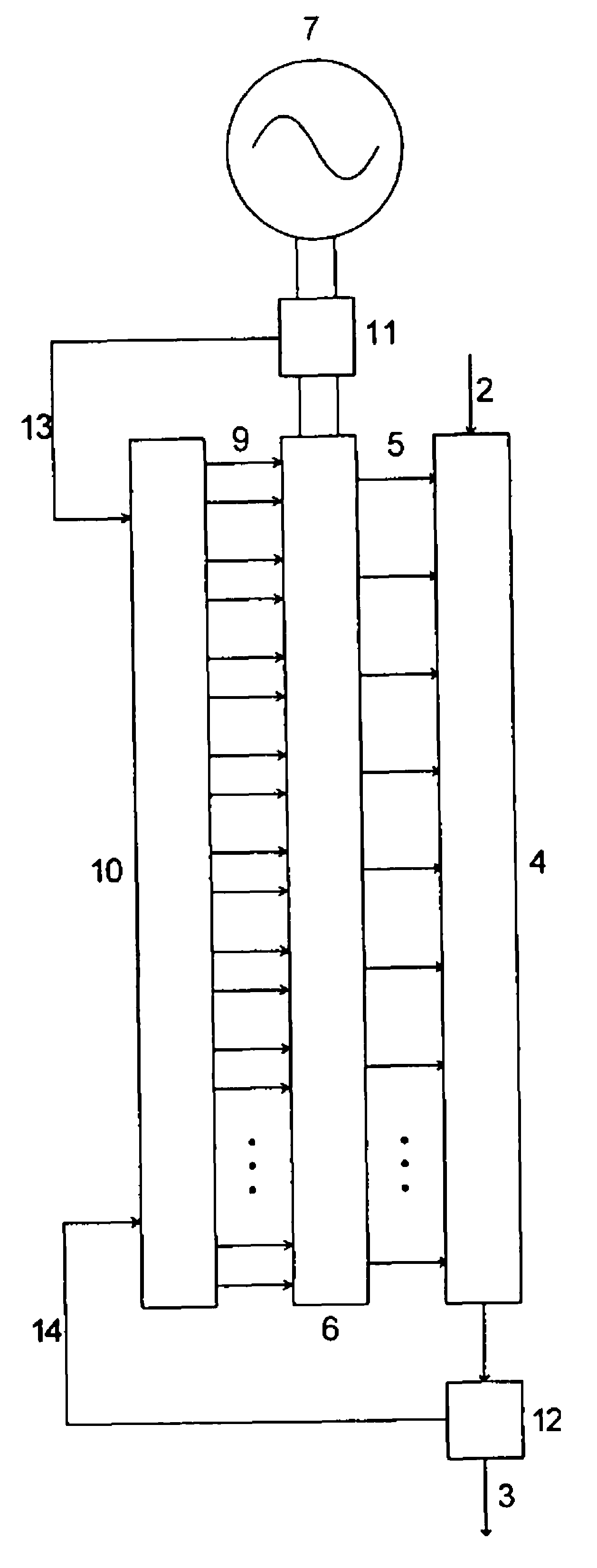
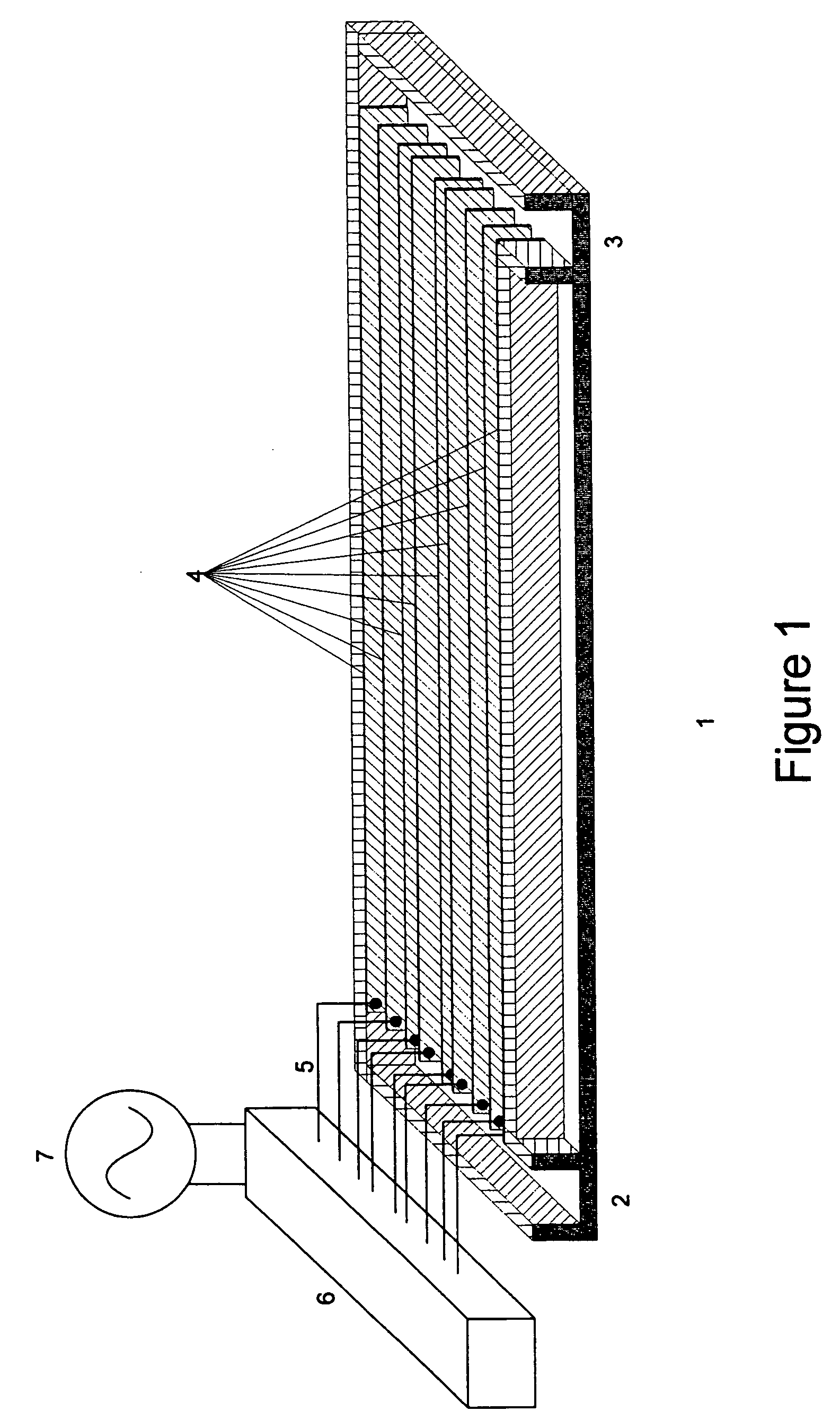
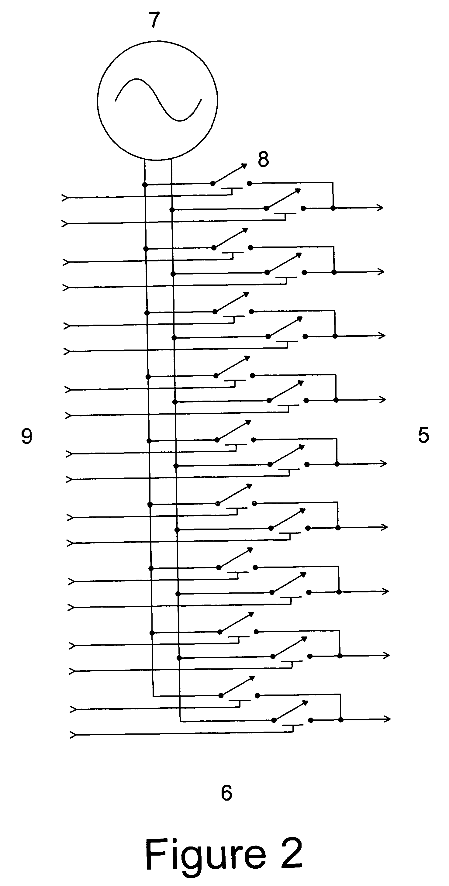
[0035]FIG. 1 shows essential elements of the present invention. A liquid heating chamber 1 is shown comprising a liquid inlet 2, a plurality of electrodes 4 (the electrode array), the electrodes defining a plurality of channels, the spaces between the electrodes, through each of which liquid flows from the liquid inlet 2 to the liquid outlet 3, the liquid being heated when it flows through the channels and a voltage is applied between electrodes. For clarity, the liquid heating chamber is shown with a bottom but without a top so that the electrodes and the channels defined by them can more clearly be seen. The electrodes 4 are shown in FIG. 1 as having a non-uniform or unequal spacing, which will be explained later. The electrodes 4 are connected via connections 5 to switch matrix 6 via which AC electrical power 7 is communicated to the electrodes. The electrodes 4 are thin relative to the width of the channels. The electrodes 4 are preferably thinner than the width of the narrowest...


PUM


Abstract

The Direct Electric Resistance Liquid Heater comprises a liquid heating chamber containing a plurality of electrodes. The electrodes are spaced apart to create a plurality of channels through which the liquid to be heated passes. The electrodes are each connected to a power supply by one or more switches. A controller controls the switches based upon data received from a temperature sensor, sensing the temperature of the liquid, and / or an electric current sensor, sensing the current utilized by the liquid heater. Selection of the number and spacing of the electrodes, and the number of switches, provides the controller with various current levels options to apply to the liquid to be heated. The current levels available due to the number and spacing of the electrodes and the number of switches, span the range from minimum current to maximum current such that the controller can incrementally increase or decrease the current applied to the liquid to be heated without disrupting other users of the same power source.

Description

[0001]This application claims the benefit of U.S. Provisional Application(s) Nos.[0002]60 / 677,552 May 4, 2005[0003]60 / 709,528 Aug. 19, 2005[0004]60 / 726,473 Oct. 13, 2005FIELD OF INVENTION[0005]This invention is directed towards an electrically powered tankless electrically conductive liquid heater that provides instant, on demand heating of the liquid.BACKGROUND OF THE INVENTION AND PRIOR ART[0006]The objectives of an electrically powered tankless liquid heating device include, at a minimum, provision of the heated liquid on demand, regulation of the temperature of the heated liquid so as not to exceed a maximum temperature set point, operation below a maximum electrical current set-point, safety of operation, minimal disturbance to the power supply and low cost to manufacture. Prior art liquid heating devices have attempted to achieve these objectives, but have been only partially able to do so.[0007]Most prior art electrically powered tankless liquid heating devices use resistance...

Claims


Application Information

Patent Timeline
Patent Type & Authority Patents(United States)
IPC IPC(8): H05B3/60
CPCF24H1/106H05B3/60H05B2203/021F24H1/10F24H1/20H05B7/144
Inventor CALLAHAN, JEREMIAH M.BARZYK, JAMES E.BOWERS, JOHN H.
Owner OHMIQ INC
Why Eureka
Try Eureka