Method and apparatus for alignment, comparison and identification of characteristic tool marks, including ballistic signatures

a tool mark and alignment technology, applied in the field of tool mark identification, can solve the problems of bullet expansion and softening of the surface of the bullet, the likelihood of the ejector going into the casing, and the particular prone to softening of the bull

Inactive Publication Date: 2010-10-26
PROKOSKI FRANCINE J
View PDF8 Cites 67 Cited by
  • Summary
  • Abstract
  • Description
  • Claims
  • Application Information

AI Technical Summary

Benefits of technology

[0068]The present invention relates to a method and apparatus for comparing patterns of marks found on ballistic items (including guns, bullets and shell casings) to determine whether they have common characteristics which would indicate that the bullet or casing has been fired from a particular weapon. The invention provides the ability to rapidly match images of an unknown ballistic item with a database of images of ballistic items including guns or ammunition fired from known weapons or unknown weapons, providing linkage between weapons or crimes or other events from which the guns, bullets or casings were recovered.

Problems solved by technology

These marks may be a result of manufacturing defects, or hand finishing done in high quality weapons.
The ejector is likely to gouge the casing.
The resulting heat causes the bullet to expand and softens its surface.
Lead bullets are particularly prone to softening.
When the ammunition used is smaller than that designed to be used in a weapon, the result is loss of energy and penetration.
In addition, since the bullet is loose within the barrel, inconsistent striations will occur on various bullets fired through the weapon.
Use, cleaning, corrosion, and intentional damage to a barrel can all affect the ability to match ammunition used in it over time.
Rust or corrosion will alter fine details.
After exiting the barrel, the bullet may receive additional distortions as it passes through various materials.
The result may be to destroy the forensic value of the bullet, or may be just to require further analysis.
These marks may be a result of manufacturing defects, or result from the hand finishing done in high quality weapons.
Revolvers retain the casings until intentionally ejected, and so are often carried away from the crime scene.
The ejector is likely to gouge the casing.
A magnum weapon can chamber a regular load, but a regular weapon cannot chamber a magnum round.
Some high-powered rifles can proper .22 caliber bullets with center core primers, but the shell casings are huge relative to this group.
However, when firing a solid lead bullet, the weapon proved a hazard to unintended secondary targets, because the penetrating power was too great.
Hollow points don't necessarily mushroom every time, and can still harm secondary targets, such as by passing through soft tissue of the target and injuring someone behind.
Lead shot has been cited by environmentalists as causing lead contamination in waterways.
Although somewhat automated, current techniques are still labor intensive, acting only to select likely matching items for manual review by a ballistics expert.
Imaging multiple groove marks at one time is difficult due to the need to focus at different depths.
Achieving proper illumination for detailed imaging is difficult with current matching systems.
The metallic nature of the items causes glare and reflection to interfere with good imaging.
Use of glancing light to highlight the relief structure interferes with distinguishing lands and grooves.
The automated analysis engines are computationally intensive and may be confused by manufacturing marks, shadow, glint, and focus.
The imagery and therefore the analysis is prone to variations due to differences in initial alignment, and to inconsistent lighting strength and direction from day to day and from lab to lab and technician to technician.
Current matching systems do not have the desired accuracy, speed, cost effectiveness, and ease of use.
Due to the 3-D nature of the ballistic items, achieving proper illumination for detailed imaging is very difficult.
The metallic nature of most of the items causes glare and reflection to interfere with good imaging.
Use of glancing light to highlight the relief structure interferes with determining which marks are lands and which are groves.
Current systems are not optimized for networking among many different users each having their own imaging system and sharing databases.
The automated analysis engine is computationally intensive.
It cannot distinguish between individual characteristics peculiar to the weapon, and manufacturing marks or incidental marks of no significance.
The imagery and therefore the analysis is prone to confusion due to inconsistent and aging lighting strength and direction from day to day and from lab to lab.
However, that feature is not always present in casings, and when it is, that procedure still allows for variations in rotational position of 5° or more.
A significant limitation to the automatic determination of matching images in a large database is the problem of distinguishing lands and grooves due to variations in the strength and directionality of the illumination.
As a result, visual images do not currently provide the capability for large database partitioning and searches based upon extraction and characterization of features.
Due to the nature of ballistic items and the distortions to which they are subjected, and to variations in illumination resulting from aging, positioning, focus, personnel, and laboratory differences, visual imaging does not provide sufficient consistency and reproducibility of feature location and characteristics to facilitate such precise matching.
Using contact sensors to accurately record finely detailed toolmarks necessarily becomes slower as the characterizing detail is smaller and requires a smaller probe and finer sampling grid for accurate recording.
To the extent replication of the set-up for imaging cannot be automated, manual intervention is required.

Method used


Image

  • Method and apparatus for alignment, comparison and identification of characteristic tool marks, including ballistic signatures
  • Method and apparatus for alignment, comparison and identification of characteristic tool marks, including ballistic signatures
  • Method and apparatus for alignment, comparison and identification of characteristic tool marks, including ballistic signatures

Examples


first embodiment

DETAILED DESCRIPTION OF THE FIRST EMBODIMENT

Using Infrared Images to Refine Visible Image Details for Ballistics Identification Image and Information Capture

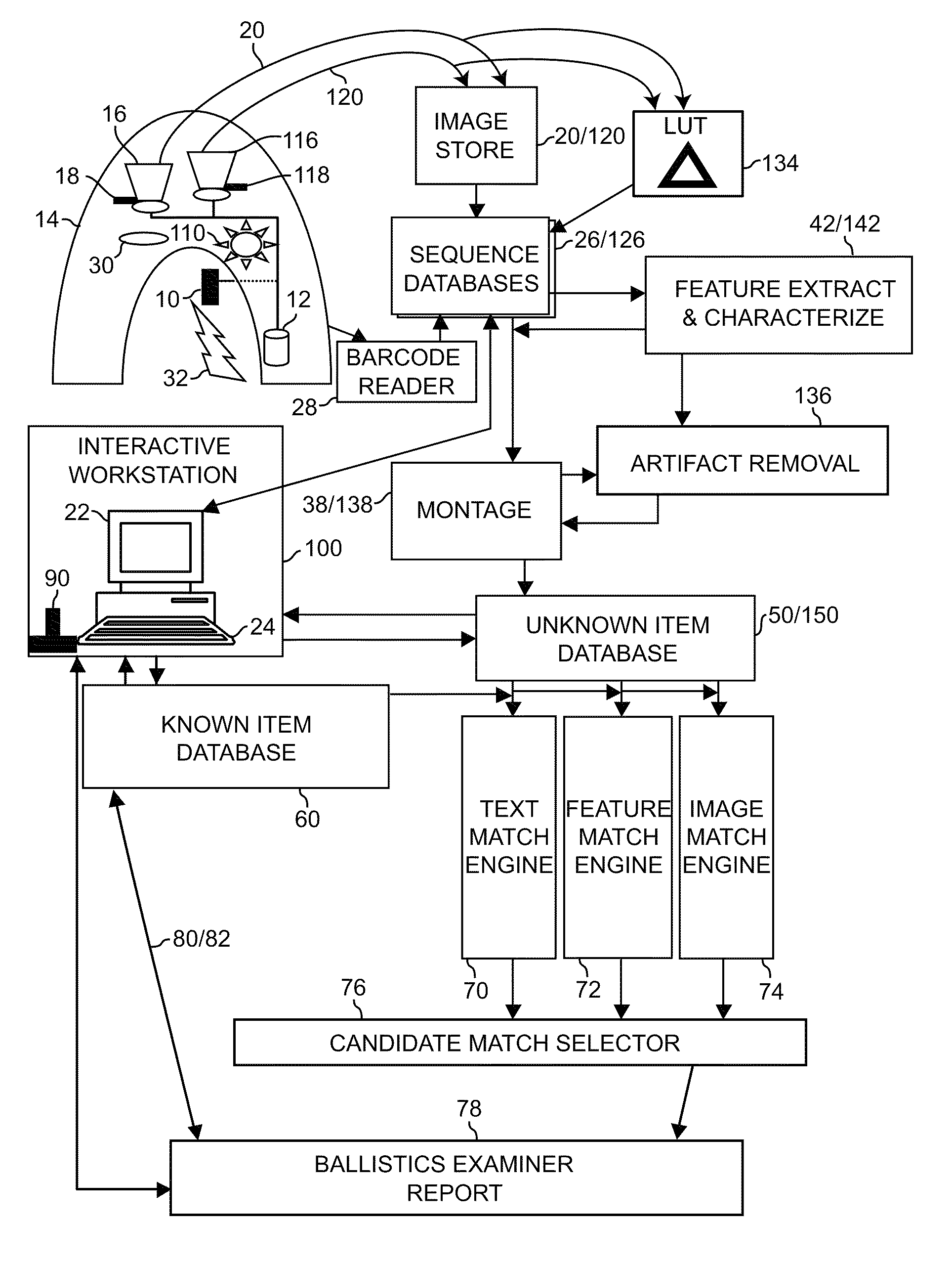
[0177]As shown in FIG. 13, a ballistic item 10 is placed in a holder 12 and surrounded by a shroud 14 covering it and an infrared camera 16 such that external lighting and heating sources are blocked. The camera focus mechanism 18 is varied over a range such that all details of the infrared image of the ballistic item are clearly captured in a sequence of infrared images 20.

[0178]Optionally, one or more spectral filters 30 can be installed and additional sequences of infrared images obtained. Optionally, a heater 32 can be used to raise the temperature of the ballistic item and additional sequences of infrared images obtained for the item at the elevated temperature and as it cools.

[0179]A controlled light source 110 is then turned on to illuminate the ballistic item and a video camera 116 is used to produce a sequence of visibl...

second embodiment

Detailed Description of the Second Embodiment

Ballistics Identification Through Matching Infrared Characteristics

[0187]When infrared imaging alone is used for ballistics identification, without use of corresponding visible images, then components 116, 118, 120, 126, 138, 142, 134, 150 and references to visible images, sequences, features, and montages can be eliminated from the apparatus description.

Image and Information Capture

[0188]A ballistic item 10 is placed in a holder 12 and surrounded by a shroud 14 covering it and an infrared camera 16 such that external lighting and heating sources are blocked. The camera focus mechanism 18 is varied over a range such that all details of the infrared image of the ballistic item are clearly captured in a sequence of infrared images 20.

[0189]Optionally, one or more spectral filters 30 can be installed and additional sequences of infrared images obtained. Optionally, a heater 32 can be used to raise the temperature of the ballistic item and ad...

third embodiment

Detailed Description of the Third Embodiment

Automation of Toolmark Identification

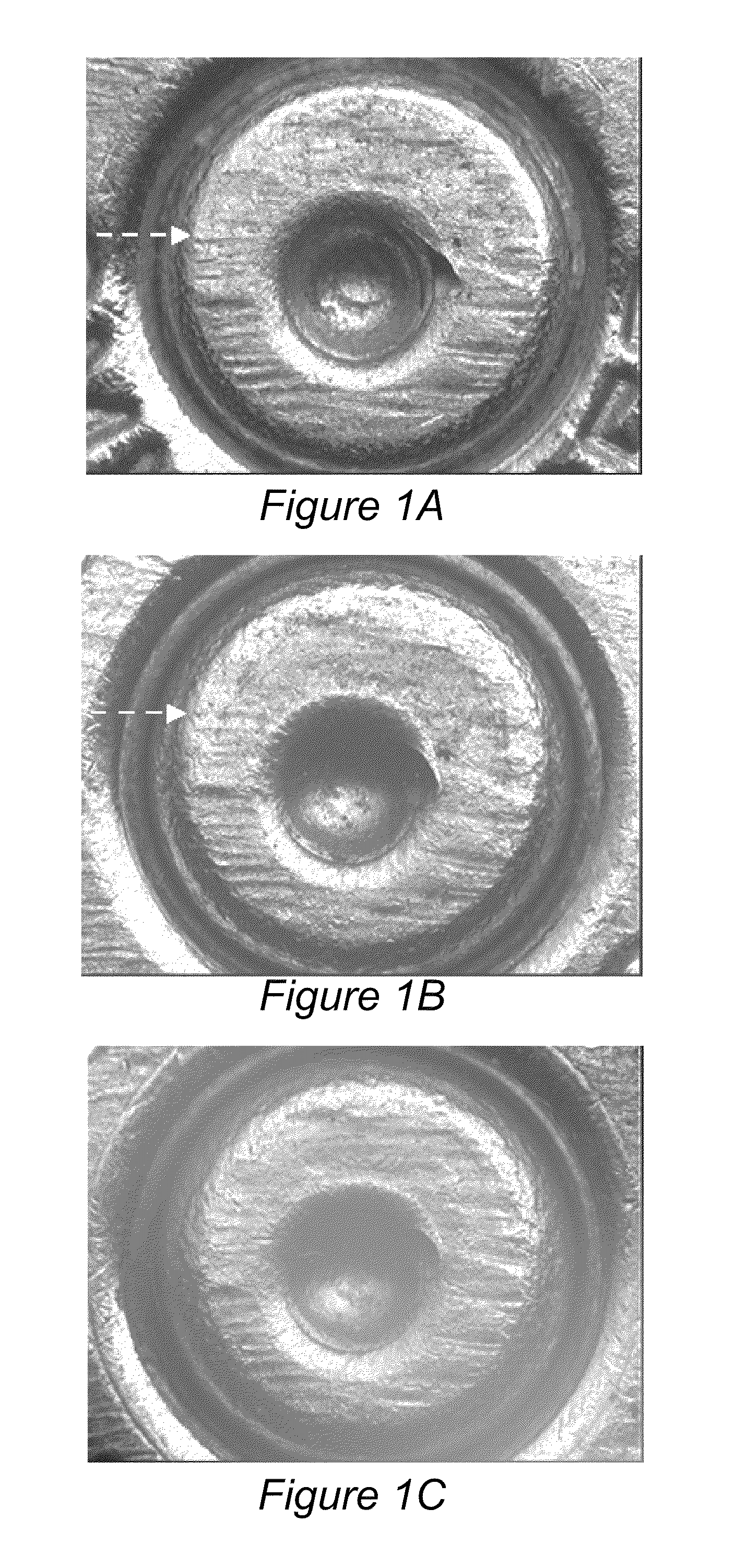
[0203]The original application, now U.S. Pat. No. 7,068,808, continued in U.S. patent application Ser. No. 11 / 319,230, specified the use of infrared imaging to capture emissivity variations induced on surfaces by the creation of toolmarks. This continuation in part specifies the use of variations in spectral emissivity within a wavelength band and temperature range selected to match the characterizing toolmark features. Infrared images display apparent temperatures that are the product of actual temperature and emissivity at each pixel location. Infrared images in which the actual temperature is uniform across the image are therefore images of emissivity differences only. Most metals and various other materials have emissivities that vary strongly with wavelength. To emphasize that infrared toolmark images contain no temperature variations they may be referred to as “spectral emissivity maps”. When wave...


PUM


Abstract

Systematic use of infrared imaging characterizes marks made on items and identifies the particular marking tool with better accuracy than use of visual imaging. Infrared imaging performed in total darkness eliminates shadows, glint, and other lighting variations and artifacts associated with visible imaging. Although normally used to obtain temperature measurements, details in IR imagery result from emissivity variations as well as thermal variations. Disturbing an item's surface texture creates an emissivity difference producing local changes in the infrared image. Identification is most accurate when IR images of unknown marks are compared to IR images of marks made by known tools. However, infrared analysis offers improvements even when only visual reference images are available. Comparing simultaneous infrared and visual images of an unknown item, such as bullet or shell casing, can detect illumination-induced artifacts in the visual image prior to searching the visual database, thereby reducing potential erroneous matches. Computer numerically controlled positioning of the toolmark relative to imaging sensors which use fixed focus optics with shallow depth of focus, varying focus distance and orientation systematically to construct a sequence of images, maximizes reliability of resulting images and their comparisons.

Description

RELATED APPLICATIONS[0001]This application is a continuation in part from, and claims priority from, U.S. patent application Ser. No. 11 / 319,230 now U.S. Pat. No. 7,602,938 Dec. 28, 2005 of the same title, which in turn claims priority from U.S. patent application Ser. No. 09 / 329,217 (now U.S. Pat. No. 7,068,808) of the same title, which in turn claims priority from U.S. Provisional Patent Application No. 60 / 087,512 filed Jun. 10, 1998.FIELD OF THE INVENTION[0002]The method and apparatus of the present invention involve tool mark identification, which is a type of forensic analysis aimed at comparing images of marks made on an item with images of marks stored in a database to find any which appear similar enough that they could have been made by the same tool. The principal purpose is to find linkage between items associated with crimes, to assist in solving the crimes. The primary application is for analysis of ballistic items, which includes guns, bullets, and shell casings.BACKGR...

Claims


Application Information

Patent Timeline
Patent Type & Authority Patents(United States)
IPC IPC(8): G06K9/00G06K9/54G06V10/143
CPCF42B35/00G06K9/00201G06K9/2018G06V20/64G06V10/143G06V20/66
Inventor PROKOSKI, FRANCINE J.
Owner PROKOSKI FRANCINE J
Why Eureka
Try Eureka