Light addressable electrochemical detection of duplex structures

a duplex structure and light-addressable technology, applied in the direction of instruments, material electrochemical variables, energy input, etc., can solve the problems of affecting the use of microchip and microarray technology in routine diagnostic and other applications, affecting the sequence of hybridization assays, and requiring cumbersome procedures

Inactive Publication Date: 2010-11-09
NORTH CAROLINA STATE UNIV
View PDF76 Cites 16 Cited by
  • Summary
  • Abstract
  • Description
  • Claims
  • Application Information

AI Technical Summary

Benefits of technology

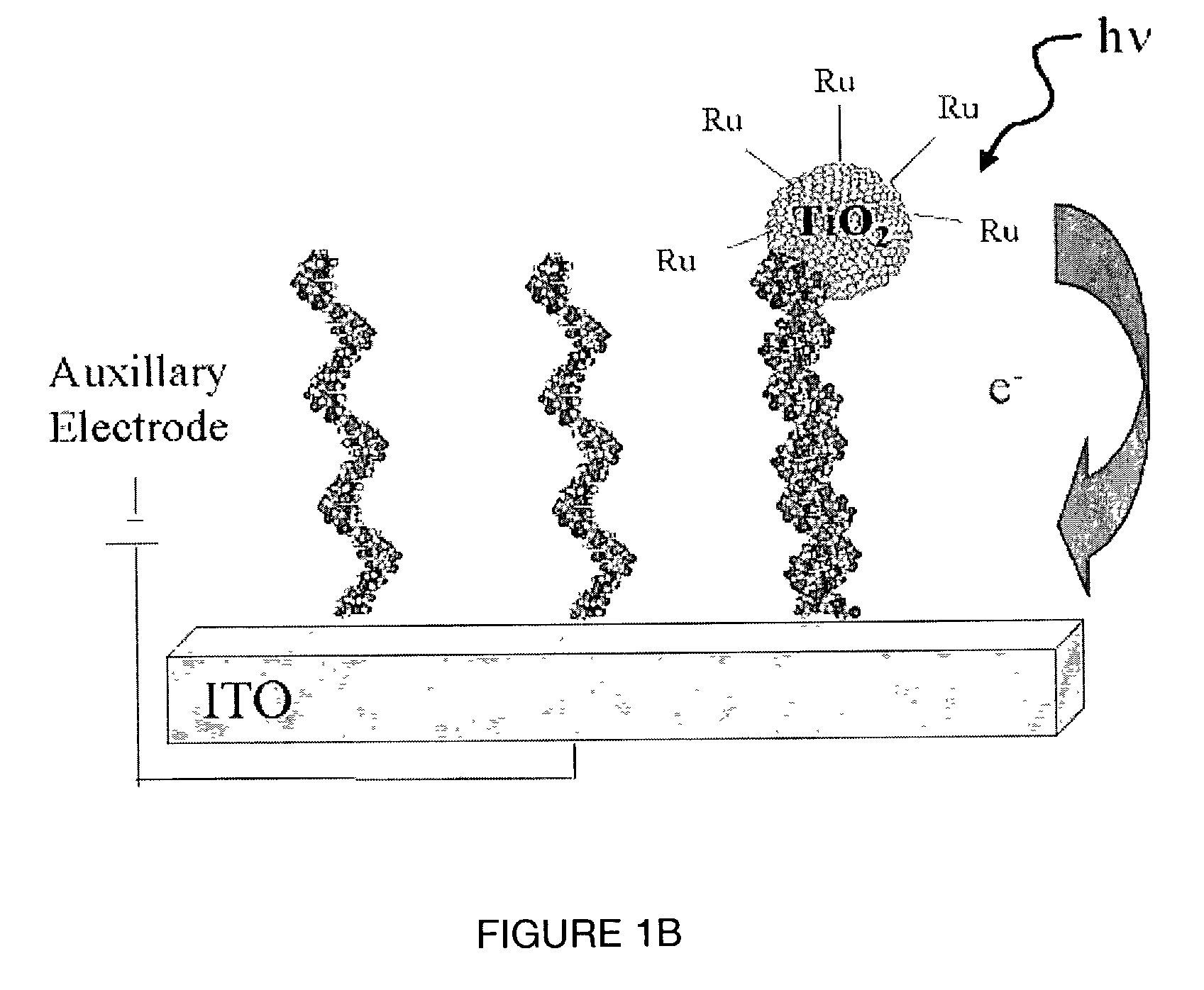
[0018]Optionally, the probe moiety is selected from the group consisting of single stranded DNA oligomer, a single stranded RNA oligomer, a peptide nucleic acid analog, double stranded DNA, a small molecule, an antibody, a polypeptide, a peptide, a synthesized target analyte, a target analyte isolated from a cell, a target analyte that is reverse transcribed from a nucleic acid sequence, a target analyte comprising intact genomic DNA, a target analyte comprising fragmented genomic DNA, mRNA, a PCR product and an OLA product. In one embodiment, the probe moiety is bound to the support in an addressable array. In another embodiment, the photoelectrochemically active moiety comprises a ruthenium center. Light sources can comprise, for example, a tungsten halogen light source, a xenon arc lamp or a laser. In yet another embodiment, the exposing is by rastering and the exposing and the detecting are performed simultaneously.

Problems solved by technology

However, non-specific binding and single / multi-base mismatches can provide a significant background signal.
Although the background intensity is often weaker for non-specific interactions, the interpretation of the hybridization assay in terms of sequence becomes much more difficult.
Protein and antibody arrays have also been developed that employ similar principles, but do not employ photocurrent-based detection methods.
This requires fluorescent labeling of the target analyte, which can be undesirable.
A number of technological barriers have inhibited the employment of microchip and microarray technology in routine diagnostic and other applications.
For example, the labeling of probe and / or target DNA with fluorescent moieties requires a cumbersome procedure and expensive detection apparatus is required for the detection of the labeled probe.
Additionally, problems with false positive signals typically associated with the read-out of chip-based hybridization assay have been an obstacle.
Moreover, hardware requirements have limited the use of microarrays useful for screening large numbers of samples.

Method used


Image

  • Light addressable electrochemical detection of duplex structures
  • Light addressable electrochemical detection of duplex structures
  • Light addressable electrochemical detection of duplex structures

Examples


example 1

Laboratory Example 1

Generation of DNA-Nanoparticle Complexes and Support-Bound DNA

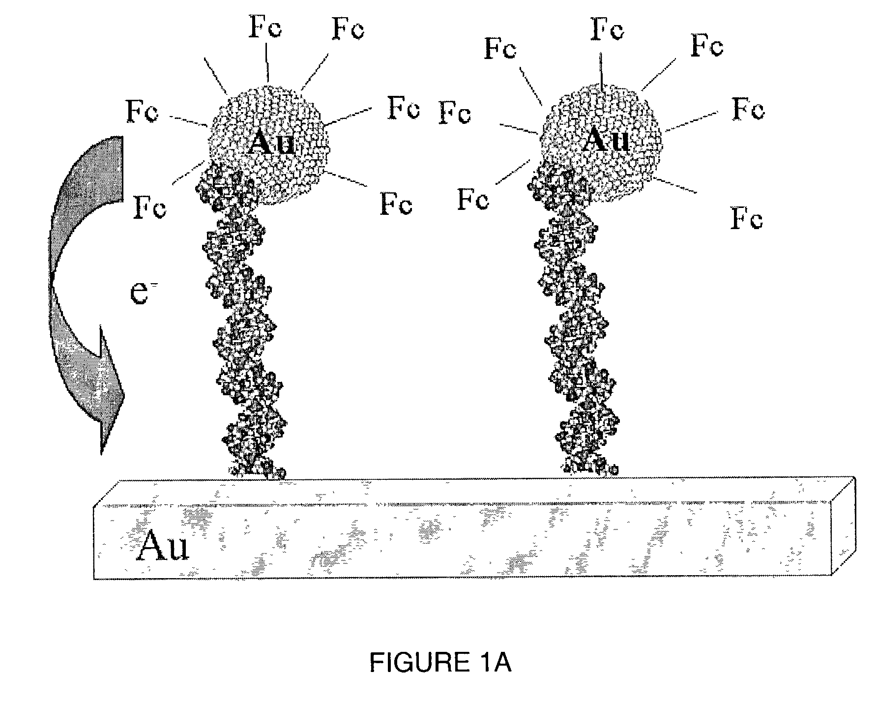
[0221]DNA-nanoparticle conjugates were synthesized to serve as targets of surface-attached DNA oligonucleotide probes. Single-stranded DNA was attached to gold particles having sizes ranging from 5 to 30 nm. Single stranded DNA was attached using methods disclosed herein. Briefly, single stranded DNA was exposed to phosphine, which attached at the 5′ terminal end of the DNA sequence. The phosphine-DNA moiety was then subjected to thiol deprotection in the presence of gold particles, whereby the single stranded DNA was bound to the gold particle.

[0222]In a separate step, complementary DNA was bound to the surface of a gold support using an alkane thiol linker, C6 mercaptohexanol in accordance with techniques described by Loweth et al., (1999) Angew. Chem. Int. Edit. 38: 1808-12, and Storhoff & Mirkin, (1999) Chem. Rev. 99: 1849-62. Briefly, solutions of single stranded DNA and C6 mercaptohexanol were pr...

example 2

Laboratory Example 2

Characterization of Nanoparticle-Containing DNA Duplexes

[0223]A height mode scanning tunneling microscopy (STM) image of (surface-bound DNA)-(DNA-nanoparticle) duplexes is shown in the lefthand panel of FIG. 3B. The righthand panel of FIG. 3B is a current mode STM image of the same DNA duplexes depicted in FIG. 3A. The duplexes were formed on the surface of a gold support, and thus demonstrate that duplexes form on a suitable support surface.

[0224]Single stranded 31 mer probe DNA sequences were bound to a gold support via reaction with C6 mercaptohexanol as described in Laboratory Example 1. The DNA sequences were commercially prepared using standard nucleic acid synthetic methods. Complementary single stranded target DNA sequences were also prepared synthetically. The target DNA was subsequently bound to nanoparticles 5 nm in size. The scheme by which the nucleic acid targets were bound to nanoparticles is presented in schematic form in FIG. 8. Generally, single...

example 3

Laboratory Example 3

Development of Experimental Controls

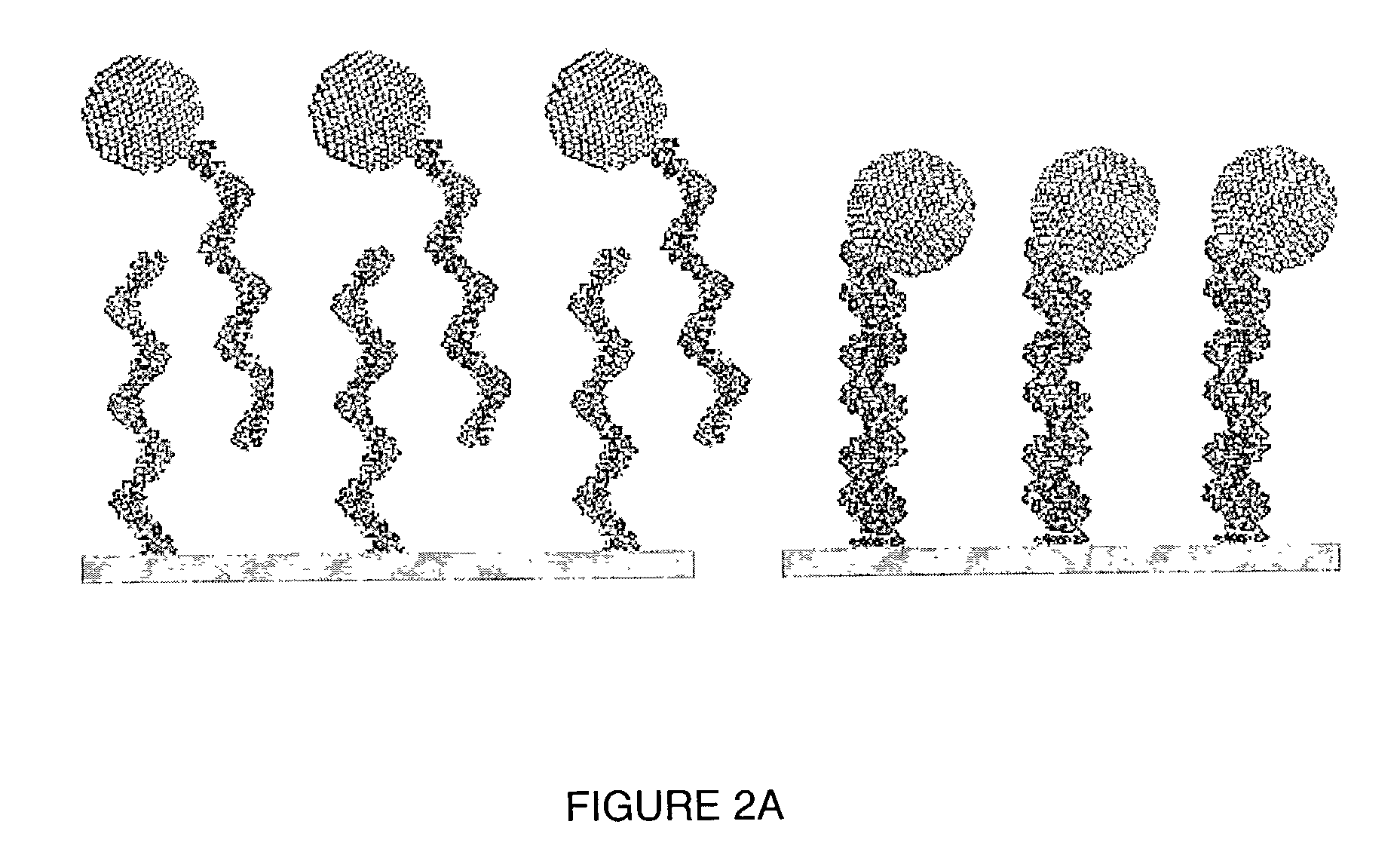
[0227]Controls were developed and employed to ensure that the nanoparticles were localized to single stranded DNA bound on the surface of the support, concurrent with the formation of DNA duplexes. Controls are helpful to show a lack of binding when a component of the system (e.g. surface-bound single stranded DNA, gold particles with single stranded DNA bound) is absent. The STM images presented in FIGS. 4A-4C show there is no adsorption of DNA-nanoparticle conjugates on surfaces where non-complementary DNA, no DNA, or only C-6 hydroxy thiols are present.


PUM

PropertyMeasurementUnit
diameteraaaaaaaaaa
diameteraaaaaaaaaa
diameteraaaaaaaaaa

Abstract

A method of detecting the presence of an analyte, such as a target nucleic acid sequence, protein sequence or small molecule, which can also be employed to detect the formation of duplex structures, is disclosed. The method can comprise nucleic acids, proteins and small molecules, employing photoelectrochemically active nanoparticles, branched polymers or other structures that carry photoelectrochemically active molecules capable of generating a photocurrent when excited by light in the presence of an electric field is disclosed. The method can be employed to detect hybridization on an array and can be employed in sequencing, mutational analysis (for example, single nucleotide polymorphisms and other variations in a population) and for monitoring gene expression by analysis of the level of expression of messenger RNA extracted from a cell. The method is applicable to the detection of antibody binding or other protein binding for analyte detection in an array format. The creation of an array addressable by light is disclosed.

Description

CROSS REFERENCE TO RELATED APPLICATIONS[0001]The present patent application is a continuation of PCT International Patent Application No. PCT / US02 / 23174 filed Jul. 22, 2002, which claims priority to U.S. Provisional Patent Application Ser. No. 60 / 307,019 entitled “LIGHT ADDRESSABLE ELECTROCHEMICAL DETECTION OF DUPLEX STRUCTURES”, which was filed Jul. 20, 2001 and is incorporated herein by reference.TECHNICAL FIELD[0002]The present invention relates to the detection of duplexes using photoelectrochemistry.[0003]AbbreviationsATPadenosine triphosphateADPadenosine diphosphatebipybipyridineBSPPbis(p-sulfonatophenyl)phenylphosphinecDNAcomplementary DNADNAdeoxyribonucleic acidEDTAethylenediaminetetraacetic acidHDPEhigh density polyethyleneHEPESN-2-hydroxyethylpiperazine-N′-2-ethanesulfonicacidITOindium tin oxidekDakilodalton(s)MES2-[N-morpholino]ethanesulfonic acidmRNAmessenger RNANDPnucleotide diphosphatenmnanometerntnucleotideNTPnucleotide triphosphateOLAoligonucleotide ligation assayPAG...

Claims


Application Information

Patent Timeline
Patent Type & Authority Patents(United States)
IPC IPC(8): C12Q1/68C07H19/00C07H21/02C07H21/04C12M1/34C12P19/34G01NG01N27/30G01N33/53G01N33/542G01N33/543
CPCB82Y5/00G01N27/305G01N33/54386Y02P20/133
Inventor FRANZEN, STEFANFELDHEIM, DANIEL L.
Owner NORTH CAROLINA STATE UNIV
Why Eureka
Try Eureka