Eureka AIR delivers breakthrough ideas for toughest innovation challenges, trusted by R&D personnel around the world.

Wind turbine electricity generating system

a technology of wind turbines and electricity generation, which is applied in the direction of wind turbines, motors, electrical equipment, etc., can solve the problems of limited land for building the towers to support such wind turbines, and high construction and maintenance costs. , to achieve the effect of high electricity generation capacity, low construction and maintenance costs, and high operational efficiency

Inactive Publication Date: 2010-11-09
MELLER MOSHE
View PDF80 Cites 27 Cited by
  • Summary
  • Abstract
  • Description
  • Claims
  • Application Information

AI Technical Summary

Benefits of technology

[0010]It is another object of some embodiments of the invention to provide a new and improved system and method for generating electricity from wind using a lighter-than-air structure which is capable of varying its operational altitude and / or adapting to different wind velocities to thereby achieve a relatively high operational efficiency and provide a relatively high electricity-generating capacity while also having low construction and maintenance costs.

Problems solved by technology

However, tall towers are expensive to build and once built, are subject to intense vibrations during operation.
Furthermore, land for building the towers to support such wind turbines is limited in view of numerous, known factors, including acquisition costs, environmental impact, zoning issues.
Although offshore winds, i.e., winds over bodies of water, are stronger than winds over land, the construction of support structures for wind turbines over a body of water is expensive, although there are significantly fewer limitations on the space for building support structures over such bodies of water.
The most notable limitation is that the construction of support structures for wind turbines is limited to certain depths of the bodies of water.
A drawback of this prior art system is that its power generation is very limited and it is not very efficient.
Among its drawbacks are that it is expensive to construct, includes complex mechanical parts and is not very practical.

Method used


Image

  • Wind turbine electricity generating system
  • Wind turbine electricity generating system
  • Wind turbine electricity generating system

Examples


first embodiment

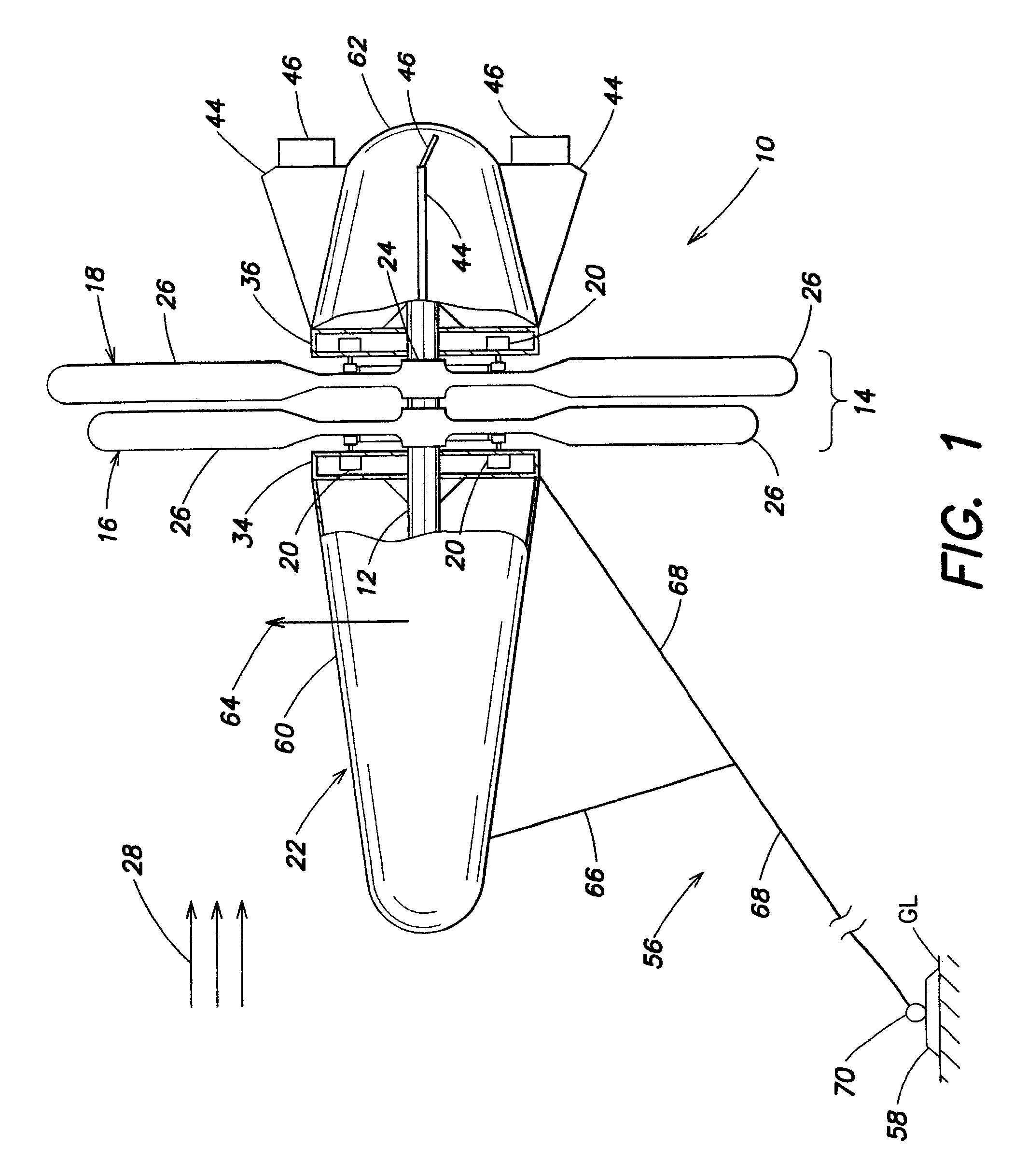
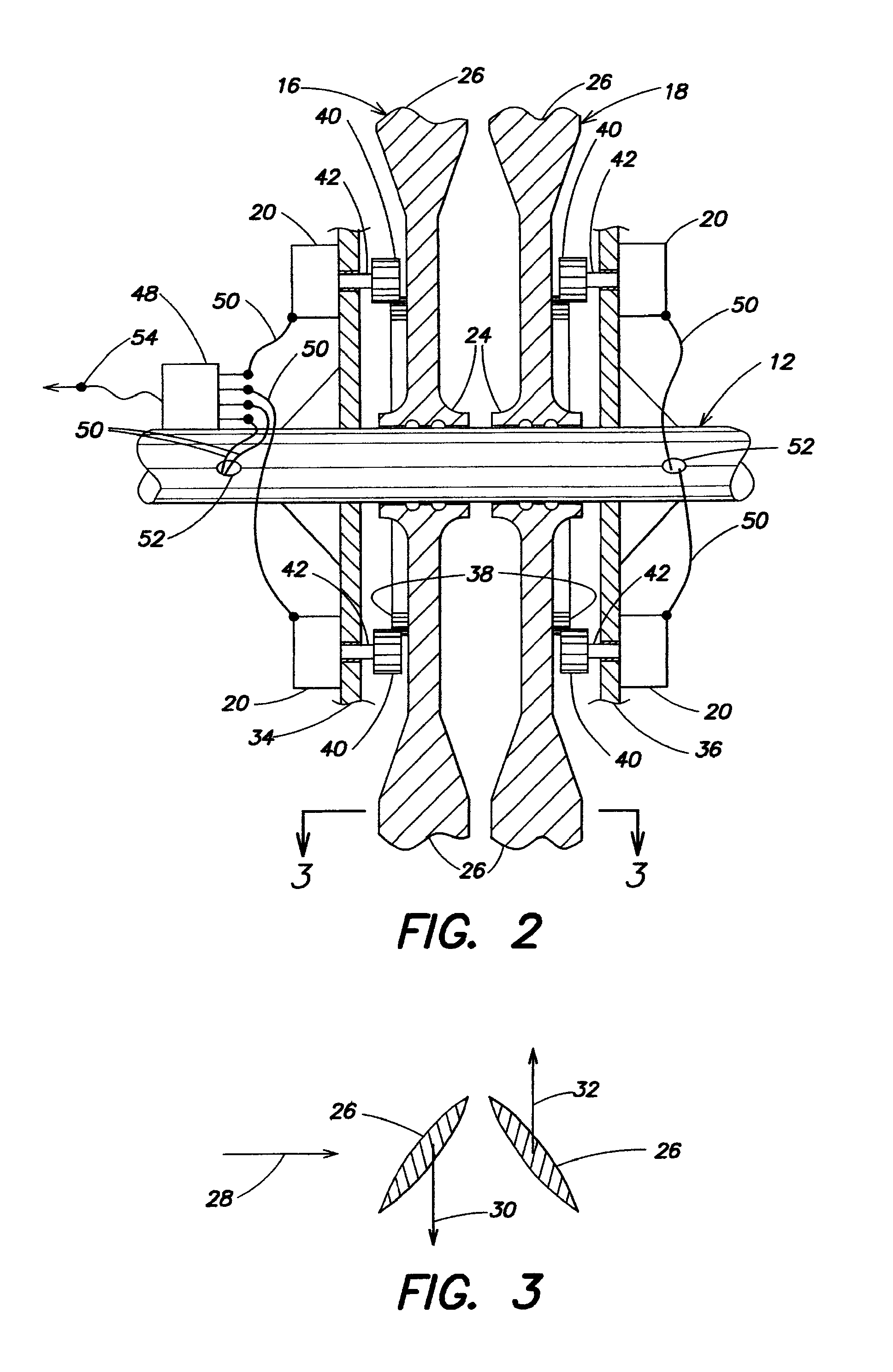
[0031]With reference to FIGS. 1-6, an airborne wind turbine system in accordance with the invention is designated generally as 10 and comprises a central shaft 12, a turbine section 14 including a front wind turbine 16 and a rear wind turbine 18 rotatably mounted to the shaft 12, generators 20 which convert rotation of the turbines 16, 18 into electricity, and a lifting structure 22 coupled to the turbine section 14 for generating a lifting force to enable the turbine section 14 to rise into the atmosphere. Although shaft 12 is referred to as a central shaft because it is preferably situated in the axial center of the system 12, it is conceivable that the shaft 12 may be positioned off-center, and thus the centrality of the shaft 12 should not be considered a limiting feature, but rather only a preferred feature.

[0032]Each of the front and rear turbines 16, 18 includes a respective bearing assembly 24 which supports the turbine 16, 18 on the central shaft 12 and a plurality of blade...

second embodiment

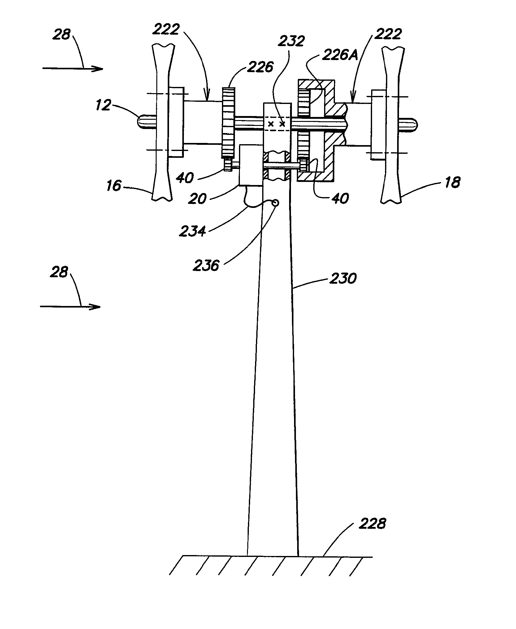
[0096]FIG. 11 shows a stationary wind turbine system in accordance with the invention that is designated generally as 240 and differs from the embodiment shown in FIG. 9 in that there is only a single generator 20 mounted to the tower structure 230, and both turbines 16, 18 are coupled to this generator 20 via a mechanical coupling. This mechanical coupling comprises two gears 40 that are fixed to or part of a common shaft 42 of the generator 20. Each gear 40 may be fixed at a respective end region of the shaft 42. The shaft 42 extends through the tower structure 230 and either clearance is provided to avoid contact between the shaft 42 and the tower structure 230 or one or more bearings are interposed between the shaft 42 and the tower structure 230. Rotation of turbine 16 in one direction and rotation of the turbine 18 in the opposite direction cause the same direction of rotation of the shaft 42 (via gears 40 and meshing gears 226, 226A).

[0097]Another advantage of having multiple...


PUM


Abstract

System for producing electricity from wind energy includes a shaft, at least two turbines rotatably mounted to the shaft and arranged to rotate independent of one another and in opposite directions when subjected to the same wind, and one or more generators that convert rotation of the turbines into electricity. The magnitude of electricity generation by the generator(s) is related to the magnitude of torque induced by the generator(s) on the shaft, and the electricity generation by the generator(s) may be controlled such that torques induced on the shaft by the generator(s) is controlled such that a sum of torques induced on the shaft is substantially zero. Generated electricity is conducted to users, to electricity storage, or to processing components. In an airborne embodiment, a lifting structure generates a lifting force to lift the turbines to a desired altitude, and an anchoring system anchors the turbines relative to the ground.

Description

CROSS REFERENCE TO RELATED APPLICATIONS[0001]This application is a continuation-in-part of International Application PCT / US2009 / 043807, with an international filing date of May 13, 2009, that claims priority of U.S. provisional patent application Ser. No. 61 / 054,397 filed May 19, 2008, now expired, and U.S. patent application Ser. No. 12 / 144,222 filed Jun. 23, 2008, now U.S. Pat. No. 7,582,981, all of which are incorporated by reference herein.FIELD OF THE INVENTION[0002]The present invention relates generally to a wind turbine system for generating electricity and more specifically to a wind turbine system for generating electricity that includes both turbines and generators on a common structure.BACKGROUND OF THE INVENTION[0003]Wind energy is one of the most readily available forms of natural energy, which include solar, hydro, geothermal energy, and is therefore often used to generate electricity. The density of wind energy, in terms of watts per square meter, is one of the highe...

Claims


Application Information

Patent Timeline
Patent Type & Authority Patents(United States)
IPC IPC(8): F03D9/00H02P9/04F03B13/10F03B13/12
CPCF03D1/025F05B2240/921F05B2240/922F05B2240/923Y02E10/725Y02E10/728F03D9/11F03D80/70F03D9/25F03D13/20F03D15/10Y02E10/72
Inventor MELLER, MOSHE
Owner MELLER MOSHE
Why Eureka
Eureka Blog
Learn More