Computer-aided bone distraction

a computer-aided, bone distraction technology, applied in the field of orthopaedic surgery, can solve the problems of inability to teach or utilize three-dimensional bone deformity or bone geometry, inability to accurately depict the complexity involved in accessing the target, and difficulty, if not impossible, to make accurate surgical plans based solely on a limited number of two-dimensional renderings of bone geometry. , to achieve the effect of reducing the frequency, reducing the cost of patients, and shortening the treatment frequency

Inactive Publication Date: 2010-11-23
CARNEGIE MELLON UNIV
View PDF21 Cites 65 Cited by
  • Summary
  • Abstract
  • Description
  • Claims
  • Application Information

AI Technical Summary

Benefits of technology

[0027]The computer assisted orthopedic surgery planner software of the present invention makes accurate surgical plans based solely on a number of two-dimensional renderings of the patient's bone geometry. The software takes into account the complex and inherently three-dimensional nature of bone deformities as well as of fixator geometry. Furthermore, three-dimensional simulation of the suggested surgical plan realistically portrays the complexities involved in accessing the target positions of the osteotomy and fixator pins surrounding the operated bone, allowing the surgeon to accurately mount the fixator on the patient according to the pre-surgical plan.
[0028]With the computer-aided pre-operative planning and frame application and adjustment methods of the present invention, the duration of fixation (of a fixator frame) may be reduced by an average of four to six weeks. Additionally, by lowering the frequency of prolonged fixations, substantial cost savings per patient may be achieved. Shortening of the treatment time and reduction of complications may lead to better surgical results and higher patient satisfaction. The use of the computer assisted orthopedic surgery planner software of the present invention (e.g., in an Internet-based bone distraction surgery planning service) may make the frame fixation and bone distraction processes physician-friendly by simplifying fixation, decreasing preoperative planning time, and reducing the chances of complications through realistic 3D simulations and bone models. Thus more surgeons may practice bone distraction, resulting in benefits to more patients in need of bone distraction.

Problems solved by technology

The entire process, however, is based on two-dimensional drawings and there is no teaching of showing or utilizing three-dimensional bone deformity or bone geometry.
It is observed that in the complex area of bone distraction surgery, it is difficult, if not impossible, to make accurate surgical plans based solely on a limited number of two-dimensional renderings of bone geometry.
Furthermore, two-dimensional depictions of surgical plans may not accurately portray the complexities involved in accessing the target positions of the osteotomy and fixator pins surrounding the operated bone.
Lack of three-dimensional modeling of these geometric complexities makes it difficult to accurately mount the fixator on the patient according to the pre-surgical plan.
The software does not provide any assistance to the surgeon about making surgical plans nor does it provide any visual feedback on how the fixator frame and bone fragments should be moved over time.
Because of the sophistication of modern fixators (e.g., the Taylor Spatial Frame) and because of the limitations of the presently available bone distraction planning and execution systems, current computerized bone distraction procedures are error-prone, even when performed by the most experienced surgeons.
Such reiterations of surgical procedures are not only time-consuming, but incur additional costs and may lead to poorer therapeutic results while unnecessarily subjecting patients to added distress.
However, it is noted at the outset that these software packages are not based on three-dimensional models.
Further, these software packages are quite limited in their capabilities to assist the surgeon in making important clinical and procedural decisions, such as how to access the site of the osteotomy or how to optimally configure fixator pin configurations.
Additional limitations of the present software systems include: (1) No realistic three-dimensional view of a bone and a fixator; (2) No usage of animation in surgical simulation; (3) Lack of an easy-to-use graphical user interface for user-friendliness; (4) No on-line database of standard or past similar cases and treatment data; and (5) No file input / output to store or retrieve previous case data.
However, the Smith software does not include any visual output to the user (i.e., the surgeon) and the user needs to enter all data via a dialog box.
However, the Smith software does not account for whether a strut can be set to all the lengths necessary during the bone correction process.
Further, the Smith software cannot calculate corrections that are due to malrotation (of the fixator) only.
The entire process, however, is based on two-dimensional drawings and there is no support for showing or utilizing three-dimensional bone deformity or bone geometry.
However, it is difficult to make accurate surgical plans based on a few such two-dimensional renderings considering the complex, three-dimensional nature of bone deformities and fixator geometry, and also considering the complexity involved in accessing the target positions of the osteotomy and fixator pins.
This inherently three-dimensional nature of bone geometry and fixator assembly also makes it difficult to accurately mount the fixator on the patient's bone according to the two-dimensional pre-surgical plan.
Additionally, the generated models are very primitive and do not show any kind of detail on the bone.
However, the graphical representations of the fixator frame and the bone by the SERF software are over-simplified.
However, this system still uses the less sophisticated and less complex Ilizarov fixator 20 (FIG. 1) instead of the more advanced Taylor Spatial Frame.
However, for use in a computer-aided bone distraction system, the Optotrak camera and additional display hardware are too expensive to consider for a widespread bone distraction commercialization strategy.
Such relative lack of popularity may be attributed to the fact that learning the techniques for bone distraction is extremely demanding and time-consuming.
Therefore, the average orthopedic surgeon does not perform these techniques.
Thus, there is a significant number of patients for whom external fixation with distraction would be the treatment of choice, but because of the current complexity and cost limitations, these patients never benefit from advanced bone distraction procedures.

Method used


Image

  • Computer-aided bone distraction
  • Computer-aided bone distraction
  • Computer-aided bone distraction

Examples


Embodiment Construction

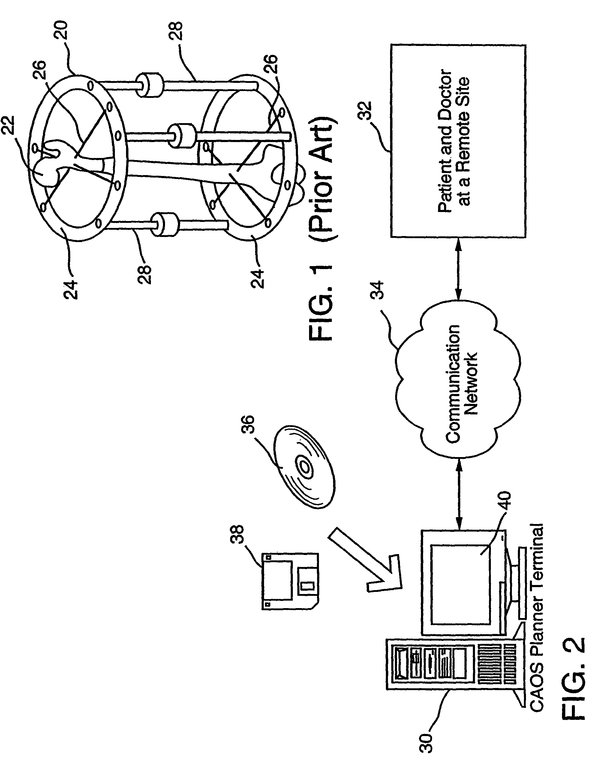
[0052]FIG. 2 depicts an exemplary setup to perform computer assisted orthopedic surgery according to the present invention. A computer assisted orthopedic surgery planner computer 30 is accessible to a surgeon in a remote operation site 32 via a communication network 34. In one embodiment, the communication network 34 may be an ethernet LAN (local area network) connecting all the computers within an operating facility, e.g., a hospital. In that case, the surgeon and the computer assisted orthopedic surgery terminal 30 may be physically located in the same site, e.g., the operating site 32. In alternative embodiments, the communication network 34 may include, independently or in combination, any of the present or future wired or wireless data communication networks, e.g., the Internet, the PSTN (public switched telephone network), a cellular telephone network, a WAN (wide area network), a satellite-based communication link, a MAN (metropolitan area network) etc.

[0053]The computer ass...


PUM


Abstract

Systems and methods of generating updated surgical plans are described herein. In one embodiment, a method of generating an updated surgical plan can include generating a three dimensional (3D) model of a bone, generating a surgical plan based on the 3D model, in which the surgical plan can include: locations on the bone upon which to dispose a fixator and settings of struts of the fixator, disposing the fixator on the bone based on the surgical plan, and, based on data associated with the placement of the fixator disposed on the bone, generating an updated surgical plan including updated settings for the struts.

Description

CROSS REFERENCE TO RELATED APPLICATIONS[0001]This application is a continuation of U.S. patent application Ser. No. 09 / 545,685 filed on Apr. 7, 2000, the contents of which application are expressly incorporated by reference herein in its entirety.BACKGROUND OF THE INVENTION[0002]1. Field of the Invention[0003]The present invention broadly relates to the field of orthopedic surgery, and more particularly, to computer assisted orthopedic surgery that uses two or more X-ray images of a patient's bone to generate a computer-based 3D (three dimensional) model of the patient's bone and a computer-based surgical plan for the doctor.[0004]2. Description of the Related Art[0005]Bone distraction in orthopedic surgery might well be considered one of the earliest successful forms of tissue engineering. Bone distraction is a therapeutic process invented in Russia in about 1951 for treating fractures, lengthening limbs and correcting other skeletal defects such as angular deformities. In bone dis...

Claims


Application Information

Patent Timeline
Patent Type & Authority Patents(United States)
IPC IPC(8): A61B5/00G06G7/48A61B6/03A61B6/02A61B17/02G06T1/00G06T15/20G06T17/10
CPCA61B17/025G06T15/20G06T17/10A61B2017/0275A61B2019/501A61B2019/5238G06T2210/41A61B2034/101A61B2090/376
Inventor KRAUSE, NORMANMENDICINO, ROBERT W.SHIMADA, KENJIWEISS, LEE E.KANADE, TAKEO
Owner CARNEGIE MELLON UNIV
Why Eureka
Try Eureka