Method for fabricating solid oxide fuel cell module

a fuel cell module and solid oxide technology, applied in the direction of cell components, final product manufacturing, sustainable manufacturing/processing, etc., can solve the problems of low productivity, poor production yield, cracking of fuel electrodes, etc., and achieve the enhancement of solid oxide fuel cell module productivity, high gas sealing performance, and cost reduction

Active Publication Date: 2010-11-23
TOKYO GAS CO LTD
View PDF16 Cites 3 Cited by
  • Summary
  • Abstract
  • Description
  • Claims
  • Application Information

AI Technical Summary

Benefits of technology

[0057]With an SOFC module of a multi-segment type, according to the invention, it is possible to solve the problems of sinterability occurring between the respective fuel electrodes, and the respective electrolytes, among the respective fuel electrodes, the respective electrolytes, and the respective interconnectors, among the substrate, the respective fuel electrodes, and the respective electrolytes, or among the substrate, the respective fuel electrodes, the respective electrolytes, and the respective interconnectors, and so forth and, further, to attain a high gas-sealing performance by virtue of the respective dense interconnectors, and the respective electrolytes, and secure electrical contact at portions of the respective interconnectors, in contact with the respective fuel electrodes. Consequently, it is possible to obtain various useful effects such as an enhancement in productivity of the solid oxide fuel cell module of the multi-segment type, and capability of achieving a reduction in cost.Constituent Material of the Interconnector
[0058]In the SOFC module, the interconnector linking the fuel electrode to the air electrode between the respective cells adjacent to each other is required to achieve an electrical continuity between the fuel electrode and the air electrode, and to be low in electrical resistance, having a high gas-sealing performance, and heat resistance at both the fuel electrode and the air electrode. With the invention, as a constituent material of the interconnector, use is made of a material meeting those requirements and, as examples of the constituent material of the interconnector, there can be cited materials described under items (1) to (4) given hereunder:
[0059](1) a mixture of a glass and an electroconductive material. Since a glass is normally an insulator, in order to cause current to flow therethrough, the surface thereof is provided with a metal such as Ag, Pt, and so forth, or a film of In2O3, or SnO2, and so forth, for utilization of the electroconductivity thereof. With the invention, as the constituent material of the interconnector, use is made of the mixture of the glass and the electroconductive material, that is, the mixture made by mixing the electroconductive material into the glass. There is no particular limitation to the kind of glass used in this case and use can be made of a glass of a network structure, including SiO2 or Al2O3 in addition to SiO2, containing K2O, ZnO, BaO, Na2O, CaO, and so forth and, for example, among soda glass, borosilicate glass, silica glass, and so forth, a suitable one may be selected for use. Use is preferably made of glass having the properties of a thermal expansion coefficient in a range of 8.0 to 14.0×10⁻⁶ K−1, and a softening point in a range of 600 to 1000° C. As the electroconductive material mixed into the glass, use is made of a metal or an electroconductive oxide. As the metal, use is made of at least one kind of metal selected from the group consisting of Pt, Ag, Au, Ni, Co, W and Pd, that is, a metal containing one kind or not less than two kinds among those metals. As an example of the case of the metal containing not less than two kinds of those metals, there can be cited an alloy containing Ag, for example, an Ag—Pd base alloy, and so forth. As an example of the electroconductive oxide, there can be cited (a) a perovskite-type ceramic composed of not less than two elements selected from the group consisting of La, Cr, Y, Ce, Ca, Sr, Mg, Ba, Ni, Fe, Co, Mn, Ti, Nd, Pb, Bi, and Cu, (b) an oxide expressed by chemical formula (Ln, M) CrO3 (in the chemical formula, Ln refers to lanthanoids, and M refers to Ba, Ca, Mg, or Sr), (c) an oxide expressed by chemical formula M (Ti1-x Nbx)O3 (in the chemical formula, M refers to at least one element selected from the group consisting of Ba, Ca, Li, Pb, Bi, Cu, Sr, La, Mg, and Ce, x=0 to 0.4) and so forth.
[0060]The electroconductive material content of the mixture of the glass and the electroconductive material is preferably not less than 30 vol. % of the mixture, in which case the interconnector can maintain an excellent electroconductivity. Further, it is preferable that the mixture of the glass and the electroconductive material is subjected to a heat treatment at not higher than the melting point of the electroconductive material after the mixture is applied between the fuel electrode of one of adjacent cells and the air electrode of the other cell.
[0061](2) an oxide containing Ti, expressed by, for example, chemical formula M(Ti1-x Nbx)O3 (in the chemical formula, M refers to at least one element selected from the group consisting of Ba, Ca, Li, Pb, Bi, Cu, Sr, La, Mg, and Ce, x=0 to 0.4)
[0062](3) a material composed mainly of Ag. In the case of this material, it is desirable to cover an interconnector made of this material with glass.

Problems solved by technology

Meanwhile, because the insulator substrate does not undergo thermal contraction, the fuel electrodes crack.
For this reason, in the fabrication of the cells, the production yield is poor and productivity is low.
In addition there has also arisen a problem that the mechanical strength of the fuel electrodes is very weak.
However, although this material, that is, (La, Sr)CrO3 has a high chemical stability in both the oxidizing and reducing atmosphere, it has been very difficult to obtain a dense sintered body out of the material, thereby obtaining high gas-sealing performance.
That is, since the material has poor sinterability, it has been difficult to implement fabrication of the interconnector out of the same with ease, and consequently, it has been impossible to secure gas-sealing performance.
Furthermore, because the material is high in electrical resistivity, use thereof has been under constraints such as the need for use after reduction in thickness thereof, or the need for use at a high temperature around 1000° C.

Method used


Image

  • Method for fabricating solid oxide fuel cell module
  • Method for fabricating solid oxide fuel cell module
  • Method for fabricating solid oxide fuel cell module

Examples


example 1

Of Configuration of Cells Disposed on a Substrate Face

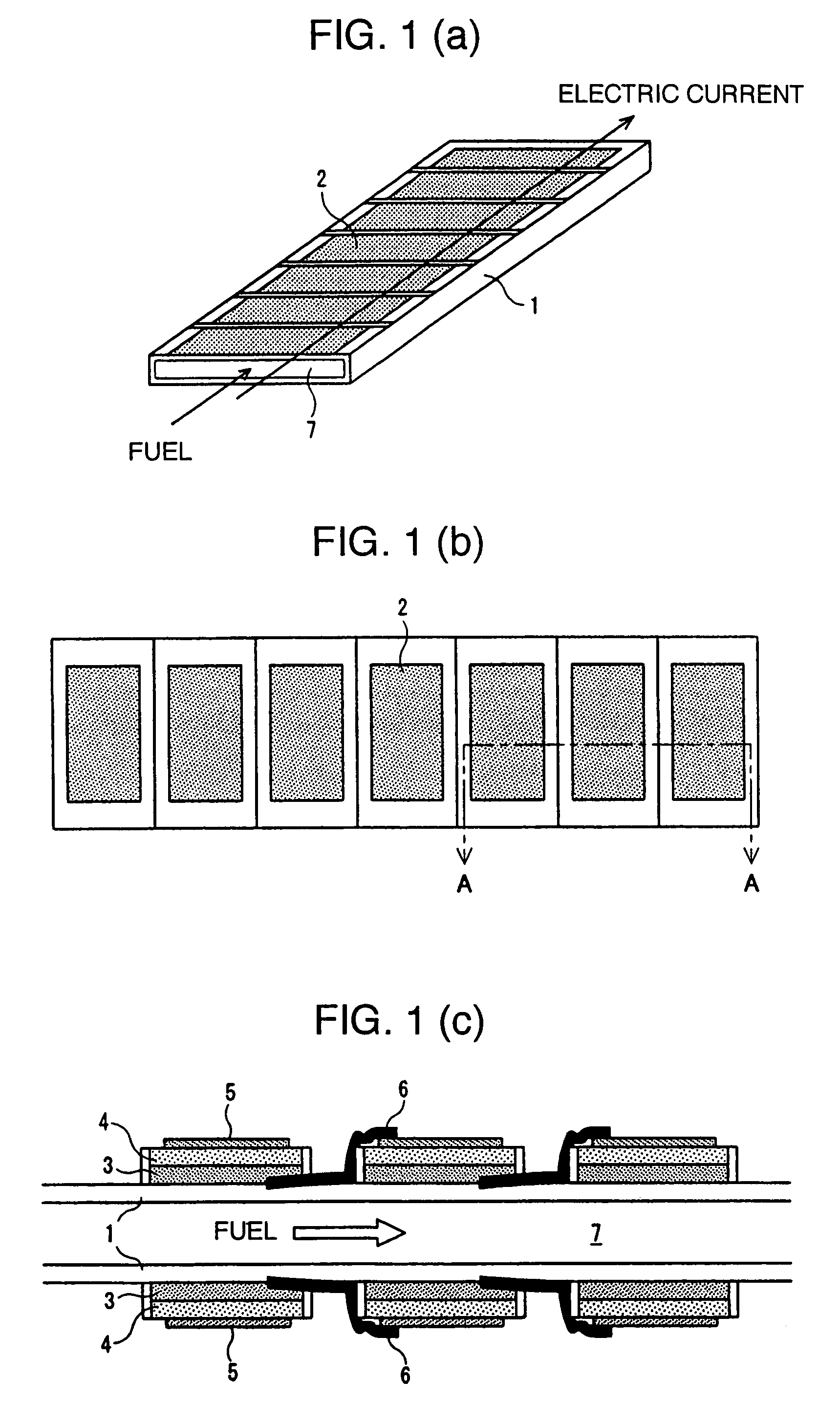
[0074]A plurality of cells each comprising a fuel electrode, an electrolyte, and an air electrode, stacked in sequence, are formed on a substrate with an internal fuel flow part provided therein, at least a face thereof in contact with the cells and interconnectors being an insulator. With the invention, respective cell areas may be the same along the direction of fuel flow as shown in FIGS. 1(a) to 1(c), or may be varied along the direction of the fuel flow as shown hereunder (refer to Example 2 of Configuration of Cells Disposed on a Substrate Face). In this connection, a cell area generally refers to an effective power generation area of a cell, and since the effective power generation area of the air electrode or the effective power generation area of the fuel electrode, whichever is smaller, is rate-limiting, the cell area refers to the smaller one of those effective power generation areas.

example 2

Of Configuration of Cells Disposed on a Substrate Face

[0075]Configuration whereby respective cell areas are varied along the direction of fuel flow has been developed by the inventor, et al., and by sequentially increasing the respective cell areas along the direction of the fuel flow, it is possible to sequentially decrease the current density and thereby enhancing the power generation efficiency. Further, since there is an increase in the number of electrical connections in series, voltage increases and conversion efficiency of conversion from direct current (DC) to alternating current (AC) can be enhanced.

[0076]FIGS. 6(a) to 6(c) are views showing the configuration according to Example 2. FIG. 6(a) is a perspective view, FIG. 6(b) a plan view, and FIG. 6(c) a sectional view taken on line A-A in FIG. 6(b), showing the configuration expanded so as to be larger than that in FIG. 6(b). As shown in FIGS. 6(a) to 6(c), on either the upper side face or the underside face, or both the fa...

example 3

Of Configuration of Cells Disposed on a Substrate Face

[0084]FIGS. 7(a) to 7(c) are views showing Example 3 of Configuration of Cells Disposed on a Substrate Face, as the target for the manufacturing method according to the invention. FIG. 7(a) is an oblique perspective view, FIG. 7(b) a plan view, and FIG. 7(c) a sectional view taken on line A-A in FIG. 7(b), showing the SOFC module expanded so as to be larger than that in FIG. 7(b). As shown in FIGS. 7(a) to 7(c), in each of a plurality of rows from the first to n-th rows, on either the upper side face or the underside face, or both the faces of an insulator substrate 21 in a rectangular or hollow-flat shape, in cross-section, there are formed a plurality of cells 22 each made up of a fuel electrode 23, an electrolyte 24, and an air electrode 25, stacked in sequence, and the adjacent cells 22 are electrically connected in series with each other through the intermediary of the respective interconnectors 26. In FIGS. 7(a) to 7(c), th...


PUM

PropertyMeasurementUnit
softening pointaaaaaaaaaa
operating temperatureaaaaaaaaaa

Abstract

A method of manufacturing a solid oxide fuel cell module involves the steps of co-sintering the respective fuel electrodes, and the respective electrolytes, subsequently forming a dense interconnector out of a dense interconnector material, or an interconnector material which turns dense by sintering in at least parts of the solid oxide fuel cell module, in contact with the respective fuel electrodes, and the respective electrolyte, and forming an air electrode on the respective electrolytes before electrically connecting the respective electrodes with the respective first parts of the interconnectors electrically connecting the respective electrodes with the respective first parts of the respective interconnectors via respective second parts of the interconnectors which have a density less than the respective first parts.

Description

TECHNICAL FIELD[0001]The invention relates to a method of manufacturing a solid oxide fuel cell module, and more specifically, to a method of manufacturing a solid oxide fuel cell module of a multi-segment type.BACKGROUND TECHNOLOGY[0002]A solid oxide fuel cell (referred to hereinafter merely as an SOFC where appropriate) is a fuel cell using an oxide as a solid electrolytic material having ionic conductivity. The fuel cell generally has an operating temperature as high as on the order of 1000° C., but there has lately been developed one having an operating temperature not higher than 800° C., for example, on the order of 750° C. With the SOFC, there are disposed a fuel electrode (that is, an anode), and an air electrode (that is, a cathode) with an electrolytic material sandwiched therebetween, thereby making up a single cell as a three-layer unit of the fuel electrode / an electrolyte / the air electrode. Although the air electrode is an oxygen electrode in the case of using oxygen as...

Claims


Application Information

Patent Timeline
Patent Type & Authority Patents(United States)
IPC IPC(8): H01M8/24H01M8/10H01M4/88B03C3/00H01M8/02H01M8/12
CPCH01M4/8885H01M8/0206H01M8/0215H01M8/0217H01M8/0226H01M8/1286H01M8/2425H01M2008/1293Y02E60/521Y02E60/525Y02P70/50Y02E60/50H01M8/2428H01M8/2404H01M8/0271
Inventor MATSUZAKI, YOSHIOFUJITA, KENJIROSAKURAI, TERUHIROOGASAWARA, KEI
Owner TOKYO GAS CO LTD
Why Eureka
Try Eureka