Laser light detector with reflection rejection algorithm

a technology of reflection rejection and laser light, applied in the field of laser light detectors, can solve the problems of reducing the operating range of the system, user may not activate the short range mode of the detector, user encountering erroneous elevation indications, etc., to achieve accurate detection of peak values, improve signal-to-noise characteristics, and reliable measurement of peak magnitudes

Active Publication Date: 2010-11-23
TRIMBLE NAVIGATION LTD
View PDF61 Cites 25 Cited by
  • Summary
  • Abstract
  • Description
  • Claims
  • Application Information

AI Technical Summary

Benefits of technology

[0013]Accordingly, it is an advantage of the present invention to provide a modulated laser light detector that can reliably measure the peak magnitudes of received laser light signals at their respective photocells, and thereby reliably indicate the correct grade or elevation where the laser signal impacts the receiver photocell elements.
[0014]It is another advantage of the present invention to provide a modulated laser light receiver that can detect the relative magnitudes or strengths of laser light impacting at least two photocell elements of the receiver unit, while using a mixer and a filter circuit to improve the signal-to-noise characteristics, and thereby more accurately detect the peak values of the modulated laser light signals impacting the photocells at greater distances.
[0015]It is a further advantage of the present invention to provide a modulated laser light detector that uses a phase locked loop and a synchronous rectifier to improve the low noise characteristics, and thereby more accurately measure the relative strengths of the incoming signals from the photocells at greater distances.
[0016]It is yet another advantage of the present invention to provide a modulated laser light detector that uses alternative detection circuitry to reduce the cost of the system, while still utilizing an improved signal-to-noise ratio by use of a superheterodyne receiver, or by using other similar elements such as a mixer and a low pass filter.
[0017]It is still another advantage of the present invention to provide a modulated laser light detector that uses a software algorithm to help reduce the cost of the system, in which a “software phase locked loop” is used instead of a hardware phase locked loop, as part of the process used for determining the beam position of the laser light striking the array of photodetector elements of the receiver.
[0018]It is yet a further advantage of the present invention to provide a modulated laser light detector that uses a software algorithm to help reduce the cost of the system, in which a software algorithm that determines the root mean square value of multiple instantaneous samples of the received laser light signals at the IF frequencies is used as part of the process used for determining the beam position of the laser light striking the array of photodetector elements of the receiver.

Problems solved by technology

Unfortunately, there is a common problem when using such laser beam detectors indoors and at short range from the laser light transmitter.
As a result, when operated with the detector in close proximity to the transmitter, very small amounts of reflected laser power are enough to trigger the laser detector, and often will produce an erroneous elevation signal.
While this reduces the problem of reflected signals, it of course also reduces the operating range of the system, which is typically an undesirable trait.
If a user does not realize that the laser transmitter-detector system is in an error-prone situation, or if the user is poorly trained or just forgets, then the user may not activate the short range mode of the detector.
In that situation, the user will encounter erroneous elevation indications with no clear method of realizing that this is the case.
Similarly, if the short range mode is enabled, and then the range between the transmitter and laser detector increases, then suddenly the system operating range will not be as expected, and the user may not realize that the “short range mode” now having been enabled has become the problem.
With regard to the third solution described above, it should be realized that the “light control film” is comparatively expensive, and moreover, this solution is not complete.
Furthermore, by design the “light control film” limits the acceptance angle of the laser detector.
This is in direct conflict with the intended operation of the “light control film” and thus use of the film is a detriment for the customer / user.

Method used


Image

  • Laser light detector with reflection rejection algorithm
  • Laser light detector with reflection rejection algorithm
  • Laser light detector with reflection rejection algorithm

Examples


Embodiment Construction

[0057]Reference will now be made in detail to the present preferred embodiment of the invention, an example of which is illustrated in the accompanying drawings, wherein like numerals indicate the same elements throughout the views.

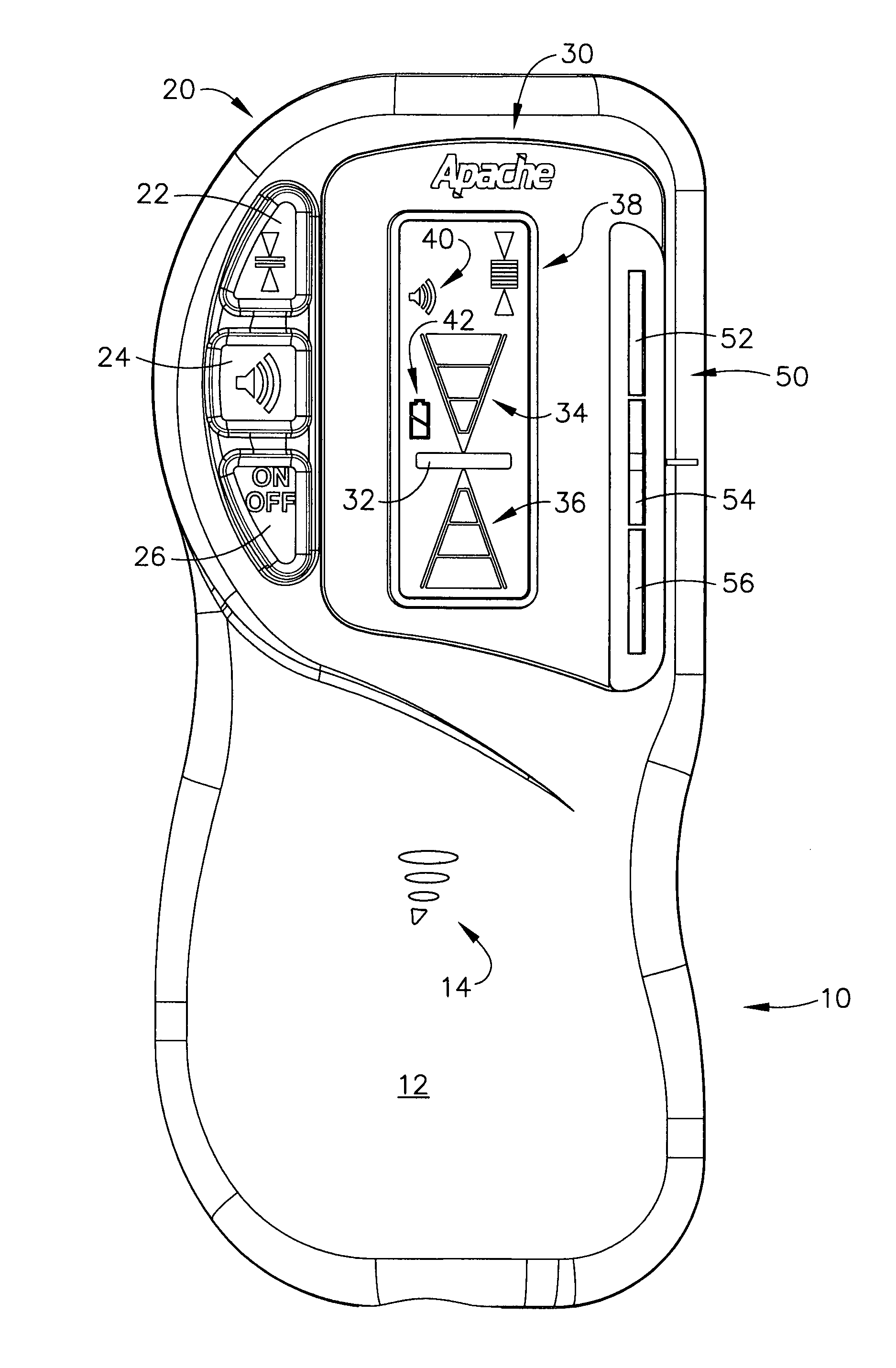
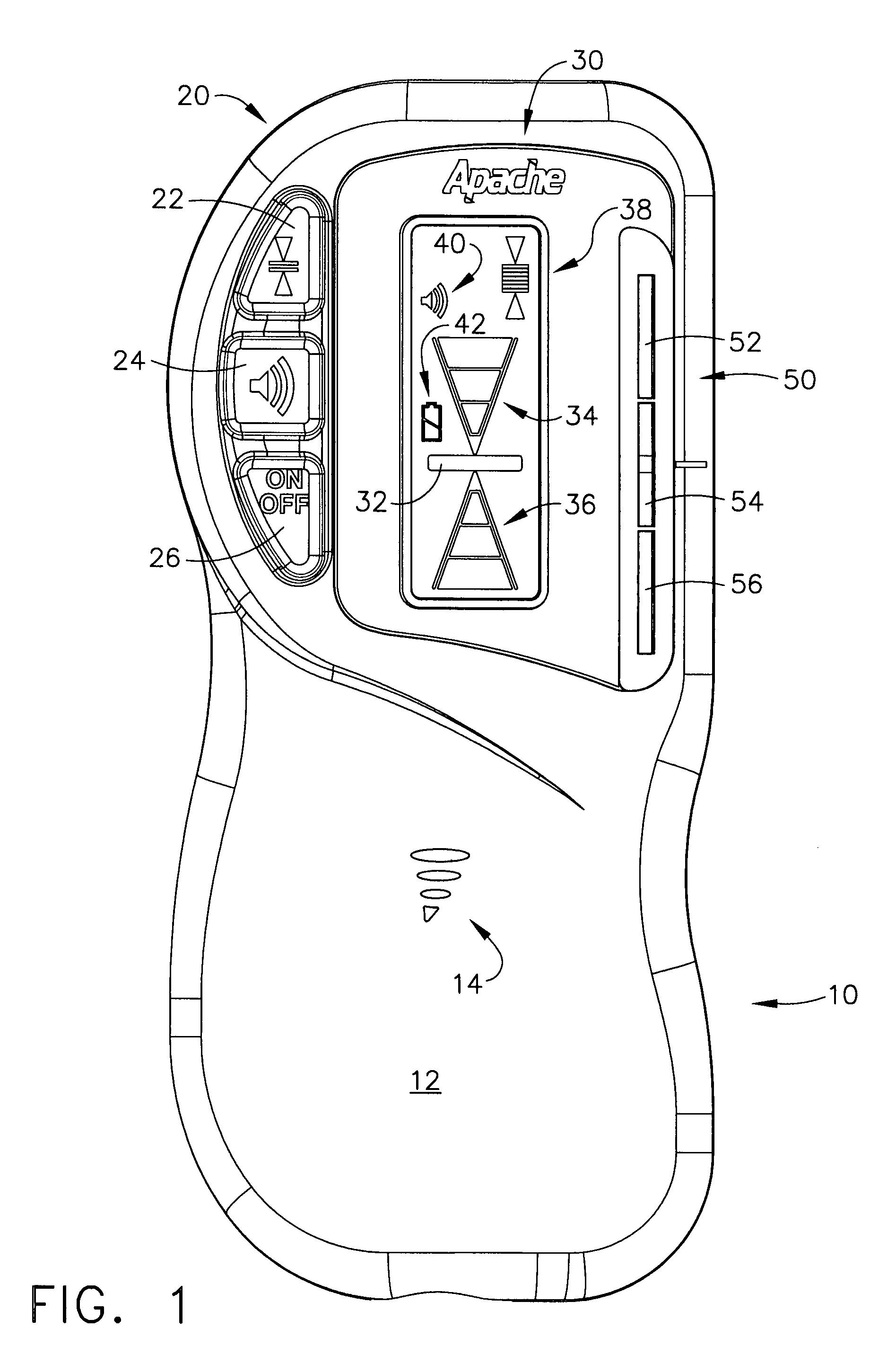
[0058]Referring now to FIG. 1, a modulated laser beam detector unit is illustrated, generally designated by the reference numeral 10. Its front outer surface at 12 is typically a plastic molded housing, which has some openings at 14 to allow for an internal beeper or other type of audio output device to be used. A set of pushbutton switches generally designated by the reference numeral 20 are located along the upper left-hand side of the case. These switches are designated by the reference numerals 22, 24, and 26, in which the top switch 22 may act as a dead band control switch on some models of laser receivers sold by Apache Technologies, Inc., the middle switch 24 enables the beeper (or other type of audio output device) to be activated, and the bottom ...


PUM


Abstract

A modulated laser light detector that converts laser light energy into electrical signals which exhibit a frequency that is substantially the same as the laser light modulation frequency, in which these signals allow the detector unit to determine a position where the laser light is impacting upon a photodiode array. A superheterodyne receiver circuit is used to provide high gain at an improved signal-to-noise ratio to improve the range at which the modulated laser light signal can be reliably detected. Various types of signal detection circuits are available. Various processing algorithms are disclosed, including one which rejects laser light strikes that are due to reflections, rather than due to a direct strike from the laser transmitter.

Description

CROSS-REFERENCE TO RELATED APPLICATIONS[0001]The present application is a continuation-in-part to application Ser. No. 11 / 414,383, titled “MODULATED LASER LIGHT DETECTOR WITH DISCRETE FOURIER TRANSFORM ALGORITHM,” filed on Apr. 28, 2006; now U.S. Pat. No. 7,323,673 which is a continuation-in-part to application Ser. No. 11 / 303,488, titled “MODULATED LASER LIGHT DETECTOR WITH MORE EFFICIENT BEAM DETECTION ALGORITHM,” filed on Dec. 16, 2005; now abandoned which is a continuation-in-part to application Ser. No. 11 / 082,041, titled “MODULATED LASER LIGHT DETECTOR WITH IMPROVED RANGE,” filed on Mar. 16, 2005 now abandoned.TECHNICAL FIELD[0002]The present invention relates generally to laser light detectors and is particularly directed to laser light detectors of the type which detect modulated laser light energy. The invention is specifically disclosed as a modulated laser light detector that converts laser light energy into electrical signals which exhibit a frequency that is substantial...

Claims


Application Information

Patent Timeline
Patent Type & Authority Patents(United States)
IPC IPC(8): G01J1/44H03F3/08H01J40/14
CPCG01J1/02G01J1/0214G01J1/0219G01J1/0271G01J1/4228G01J1/4257G01J1/44G01J2001/4242G01C15/006
Inventor AKE, DUWAIN K.
Owner TRIMBLE NAVIGATION LTD
Why Eureka
Try Eureka