Apparatus for reproducing signal from multi-layered optical disk using multiple photo detectors

a multi-layer optical disk and photo detector technology, applied in the field of optical pickup apparatuses and optical disk apparatuses, can solve the problems of deterioration of the signal reproduced from a selected record layer, drop in and the s/n ratio of the reproduced signal may thus deteriorate, so as to achieve sufficient precision and satisfactory precision

Inactive Publication Date: 2010-12-14
RICOH KK
View PDF22 Cites 2 Cited by
  • Summary
  • Abstract
  • Description
  • Claims
  • Application Information

AI Technical Summary

Benefits of technology

[0015]According to at least one of the embodiments, a light beam emitted from the light source is shone on the optical disk having two recording layers (first recording layer and second recording layer), and a returning light beam inclusive of light reflected by the first recording layer and light reflected by the second recording layer enters the light condensing unit. The light condensing unit turns the returning light into a condensing light beam. A partial light beam that is part of the condensing light beam is then detected by one or more photo detectors. The one or more photo detectors is situated between the condensing point of the light reflected by the first recording layer contained in the partial light beam and the condensing position of the light reflected by the second recording layer contained in the partial light beam, and have a first photo detecting section to detect the light reflected by the first recording layer and a second photo detecting section to detect the light reflected by the second recording layer. With this provision, the light reflected by the first recording layer and the light reflected by the second recording layer are obtained separately from each other without mutual interference. This achieves highly precise separation of reflected light beams traveling from the two recording layers of the optical disk.
[0028]This optical disc apparatus is provided with the optical pickup apparatus as described above, so that the signal obtaining unit can easily obtain the signal from the selected one of the two recording layers, resulting in the reproducing unit reproducing information recorded in the selected one of the two recording layers with sufficient precision. That is, the reproduction of information from an optical disk having two recording layers is successfully performed with satisfactory precision.
[0032]The optical disc apparatus described above is provided with the optical pickup apparatus having the drive unit, and the drive control unit controls the drive unit according to which one of the two recording layers is selected for reproduction. This provides for the signal selecting unit to easily select an output signal including only the signal from the selected one of the two recording layers among the output signals of the optical pickup apparatus. As a result, the reproducing unit can reproduce information recorded in the selected one of the two recording layers with sufficient precision. That is, the reproduction of information from an optical disk having two recording layers is successfully performed with satisfactory precision.
[0034]The optical disc apparatus described above is provided with the optical pickup apparatus having the opto-electrical device, and the switching unit controls the refractive index of the opto-electrical device according to which one of the two recording layers is selected for reproduction. This provides for the signal selecting unit to select an output signal including only the signal from the selected one of the two recording layers among the output signals of the optical pickup apparatus. As a result, the reproducing unit can reproduce information recorded in the selected one of the two recording layers with sufficient precision. That is, the reproduction of information from an optical disk having two recording layers is successfully performed with satisfactory precision.

Problems solved by technology

In the multi-layered disks, a wide gap between the record layers may cause deterioration of a signal reproduced from a selected record layer due to the effect of spherical aberration.
The S / N ratio of the reproduced signal may thus deteriorate.
The apparatuses disclosed in Patent Document 1 through Patent Document 3, however, allow signal light and aberrant light to interfere with each other prior to reaching the photo detecting surface of the photo detecting device.
This causes fluctuation in the amount of received light with respect to individual photo detecting devices, which may result in a drop in the S / N ratio of the reproduced signal.

Method used


Image

  • Apparatus for reproducing signal from multi-layered optical disk using multiple photo detectors
  • Apparatus for reproducing signal from multi-layered optical disk using multiple photo detectors
  • Apparatus for reproducing signal from multi-layered optical disk using multiple photo detectors

Examples


first embodiment

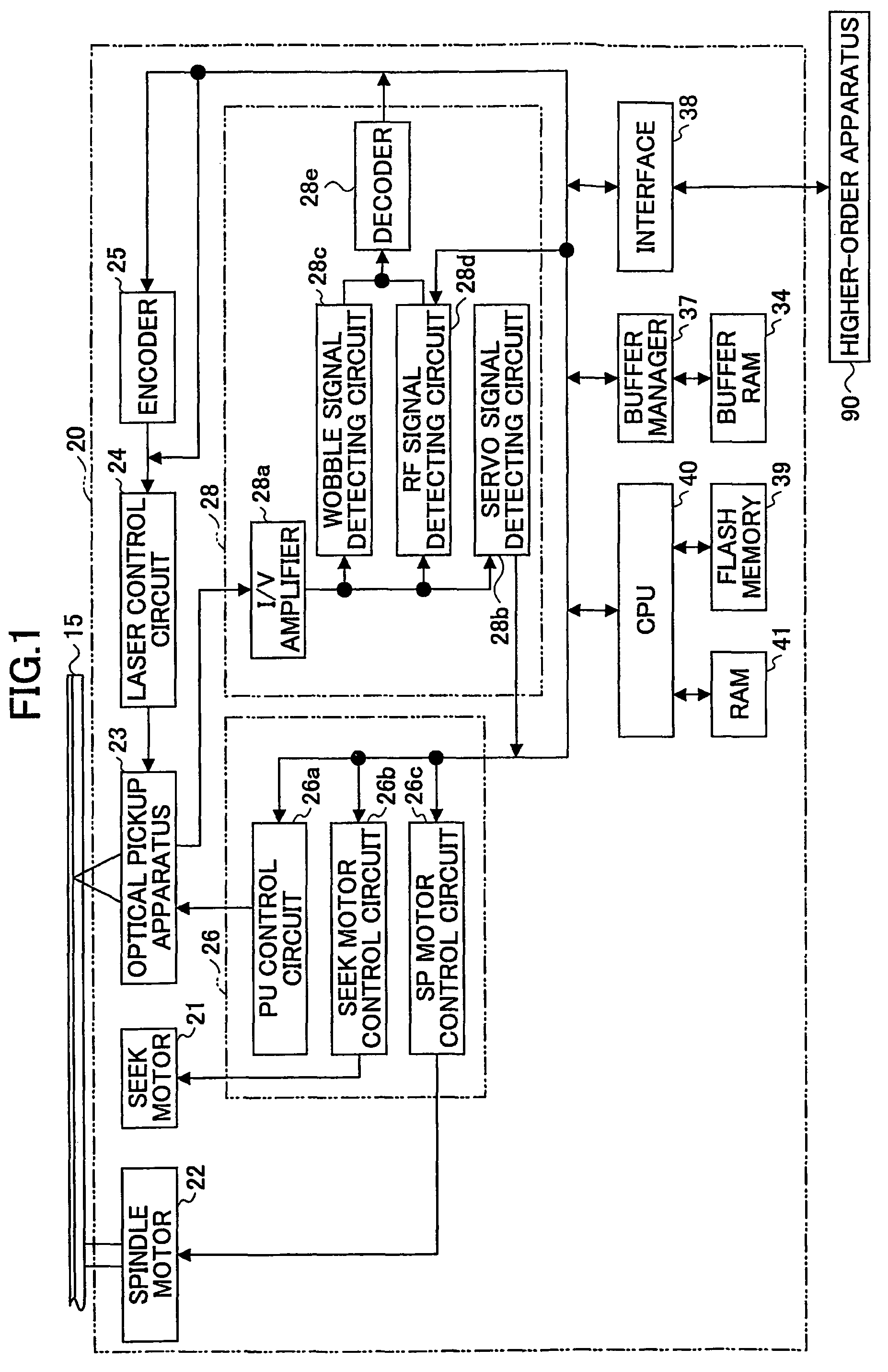
[0081]A first embodiment of the present invention will be described with reference to FIG. 1 through FIG. 10. FIG. 1 is a drawing showing a schematic configuration of an optical disc apparatus 20 according to the first embodiment.

[0082]The optical disc apparatus 20 shown in FIG. 1 includes a spindle motor 22 for revolving an optical disk 15, an optical pickup apparatus 23, a seek motor 21 for driving the optical pickup apparatus 23 in the sledge direction, a laser control circuit 24, an encoder 25, a servo control circuit 26, a reproduced signal processing circuit 28, a buffer RAM 34, a buffer manager 37, an interface 38, a flash memory 39, a CPU 40, and a RAM 41. Arrows shown in FIG. 1 only illustrate the flows of main signals and information items, and are not intended to represent all the connections between the blocks.

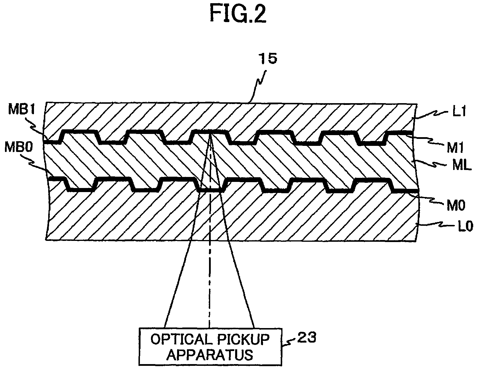
[0083]According to the first embodiment, the optical disc apparatus 20 is designed to conform to an optical disk having two recording layers, for example. That is,...

second embodiment

[0130]In the following, a description will be given of a second embodiment of the present invention with reference to FIG. 1 through FIG. 14C.

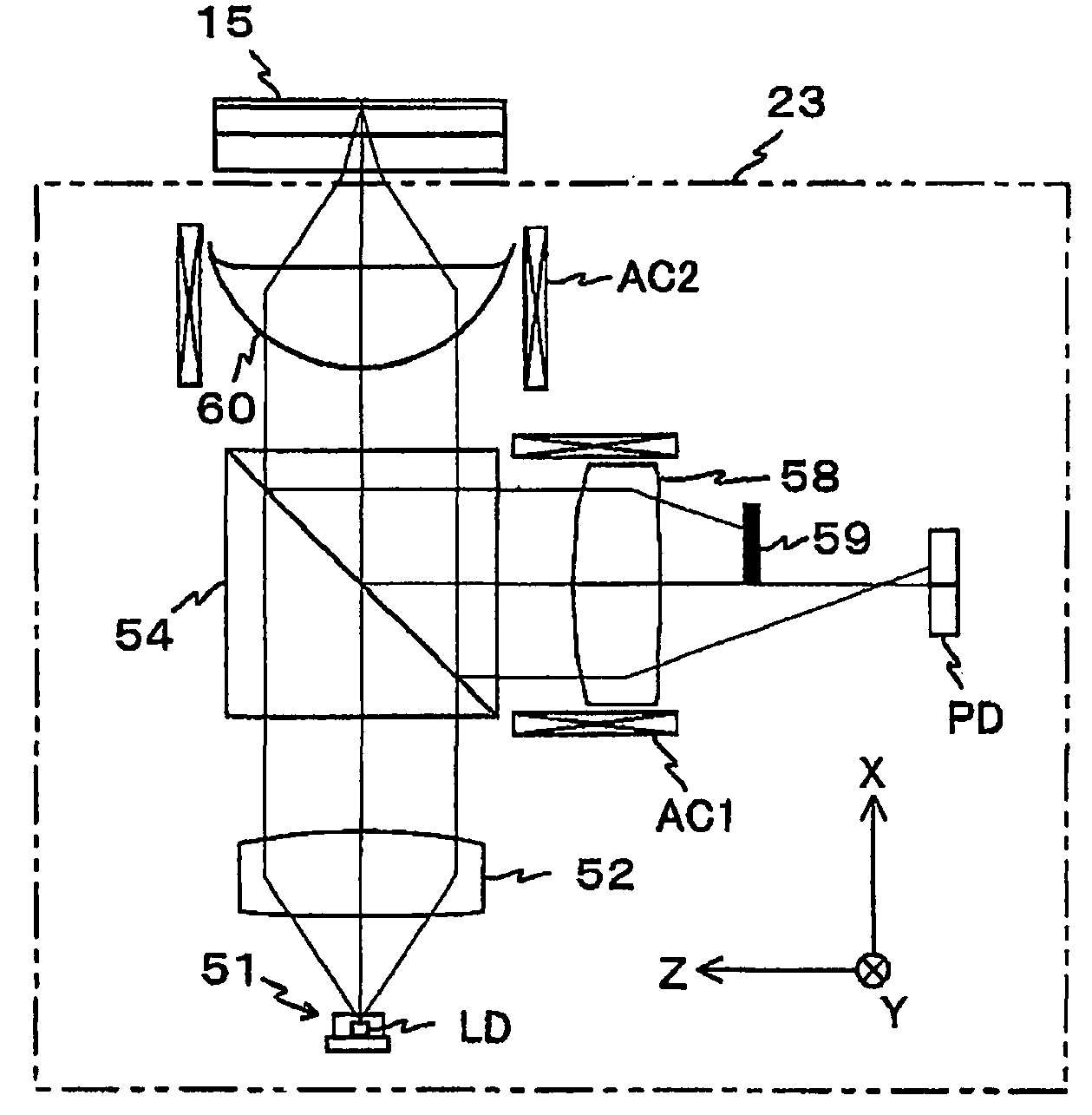
[0131]The second embodiment is a variation of the first embodiment. The second embodiment differs from the first embodiment in that, as shown in FIG. 11 serving as a non-limiting example, the photo detector PD is driven rather than driving the condenser lens 58 in the optical pickup apparatus 23. Namely, a photo detector actuator AC3, in place of the condenser lens actuator AC1, is provided as a means to drive the photo detector PD in the direction of the optical axis of the photo detecting surface. Consequently, as shown in FIG. 12 serving as a non-limiting example, the PU control circuit 26a includes a PDACT control circuit 267 for generating a signal (hereinafter referred to as a fourth drive signal for sake of convenience) for driving the photo detector actuator AC3. The PDACT control circuit 267 is provided in place of the condenser lens ...

third embodiment

[0141]In the following, a description will be given of a third embodiment with reference to FIG. 15 through FIG. 18B.

[0142]The third embodiment is a variation of the first embodiment. The third embodiment differs from the first embodiment in that a liquid crystal device pp serving as an opto-electrical device having its refractive index changing in response to an applied voltage is provided between the light blocking plate 59 and the photo detector PD in the optical pickup apparatus 23 as shown in FIG. 15 serving as a non-limiting example, and in that the condenser lens actuator AC1 is not provided. Consequently, as shown in FIG. 16 serving as a non-limiting example, the PU control circuit 26a includes a PP refractive index switching circuit 269 serving as a switching means for generating a voltage signal applied to the liquid crystal device PP. The PP refractive index switching circuit 269 is provided in place of the condenser lens ACT control circuit 265. Most other aspects of the...


PUM

PropertyMeasurementUnit
wavelengthaaaaaaaaaa

Abstract

An optical pickup apparatus for shining light on and detecting reflected light from an optical disk having two recording layers. The apparatus includes a light source, an optical system situated on a path of a light beam returning from the optical disk, the optical system including a light condensing optical unit, a light beam regulating unit, and one or more photo detectors, situated between a position where the light reflected by the first recording layer contained in the partial light beam is condensed and a position where the light reflected by the second recording layer contained in the partial light beam is condensed, the one or more photo detectors having a first photo detecting section to detect the light reflected by the first recording layer and a second photo detecting section to detect the light reflected by the second recording layer.

Description

TECHNICAL FIELD[0001]The present invention generally relates to optical pickup apparatuses and optical disk apparatuses. The present invention particularly relates to an optical pickup apparatus which shines a light beam on an optical disk having two recording layers to receive reflected light from the optical disk, and also relates to an optical disc apparatus which performs at least reproduction of information from an optical disk having two recording layers among recording, reproducing, and erasing of information.BACKGROUND ART[0002]With the recent development of the digital technology and improvement of data compression technologies, optical disks such as DVDs (digital versatile disks) have been attracting attention as a record medium for recording information such as music, movies, photographs, computer software, etc. (hereinafter also referred to as “contents”). As the price of optical disks goes down, optical disc apparatuses that use the optical disks as information recordin...

Claims


Application Information

Patent Timeline
Patent Type & Authority Patents(United States)
IPC IPC(8): G11B7/00G11B7/005G11B7/131G11B7/135G11B7/1381
CPCG11B7/131G11B7/1381G11B2007/0006G11B2007/0013
Inventor OGATA, TETSUYA
Owner RICOH KK
Why Eureka
Try Eureka