Control apparatus for linear compressor

a linear compressor and control apparatus technology, applied in the direction of motor/generator/converter stopper, dynamo-electric converter control, instruments, etc., can solve the problems of linear compressor overload or abnormal operation, linear compressor efficiency decline, linear compressor pressure and temperature increase in the limited space, etc., to prevent an inrush current

Inactive Publication Date: 2010-12-28
LG ELECTRONICS INC
View PDF27 Cites 11 Cited by
  • Summary
  • Abstract
  • Description
  • Claims
  • Application Information

AI Technical Summary

Benefits of technology

[0022]The present invention is achieved to solve the above problems. An object of the present invention is to provide a control apparatus for a linear compressor which can control an output by varying the whole capacitance and prevent an inrush current.Technical Solution
[0023]Another object of the present invention is to provide a control apparatus for a linear compressor which can prevent an inrush current by controlling a power on / off switch of the linear compressor in variation of a capacitance.
[0024]Yet another object of the present invention is to provide a control apparatus for a linear compressor which can prevent increase or decrease of an output by variation of applied power.

Problems solved by technology

Actually, as the load increases, the pressure and temperature of the refrigerants increase in the limited space.
If the power is excessively applied, the linear compressor undergoes an overload or performs an abnormal operation.
As a result, efficiency of the linear compressor decreases.
It is a fatal problem in the operation of the linear compressor.

Method used


Image

  • Control apparatus for linear compressor
  • Control apparatus for linear compressor
  • Control apparatus for linear compressor

Examples


first embodiment

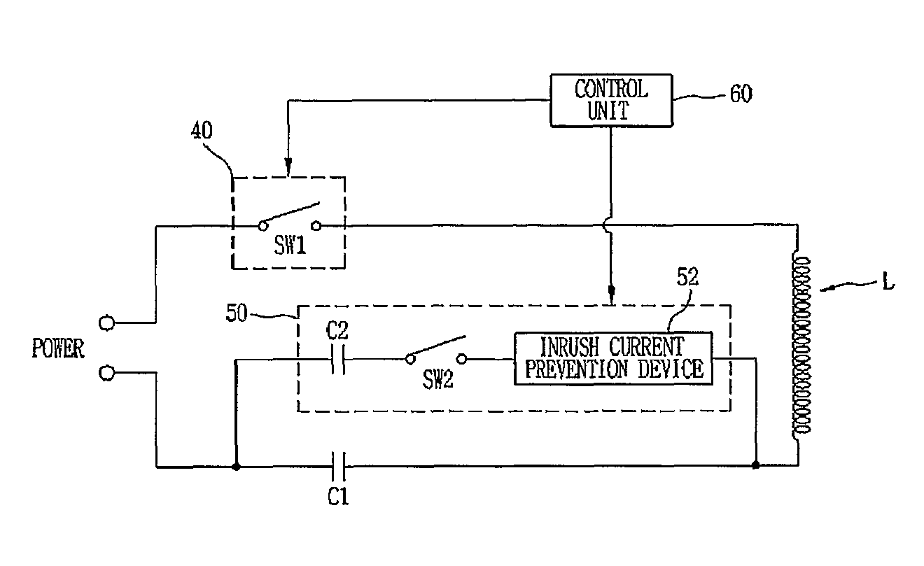
[0063]FIG. 3 is a circuit view illustrating a control apparatus for a linear compressor in accordance with the present invention.

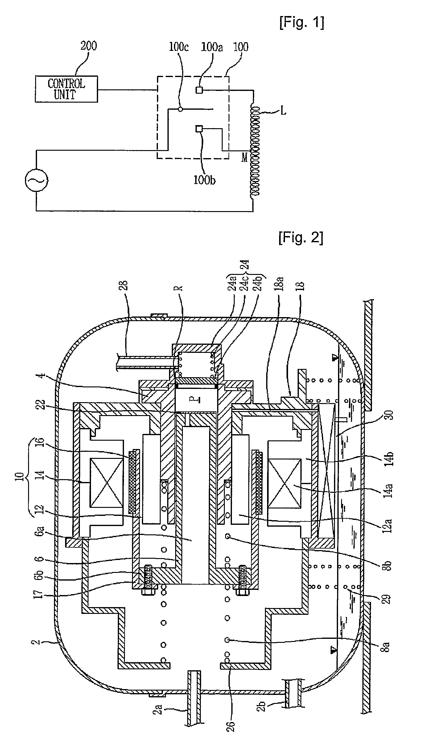
[0064]Still referring to FIG. 2, the linear motor 10 includes an inner stator 12 formed by laminating a plurality of laminations 12a in the circumferential direction, and fixed to the outer portion of the cylinder 4 by the frame 18, an outer stator 14 formed by laminating a plurality of laminations 14b in the circumferential direction around a coil winding body 14a formed by winding a coil, and installed at the outer portion of the cylinder 4 by the frame 18 with a predetermined gap from the inner stator 12, and a permanent magnet 16 disposed at the gap between the inner stator 12 and the outer stator 14, and connected to the piston 6 by the connection member 17. The coil winding body 14a can be fixed to the outer portion of the inner stator 12.

[0065]As shown in FIG. 3, the control apparatus for the linear compressor includes an on / off switch SW140 for rec...

second embodiment

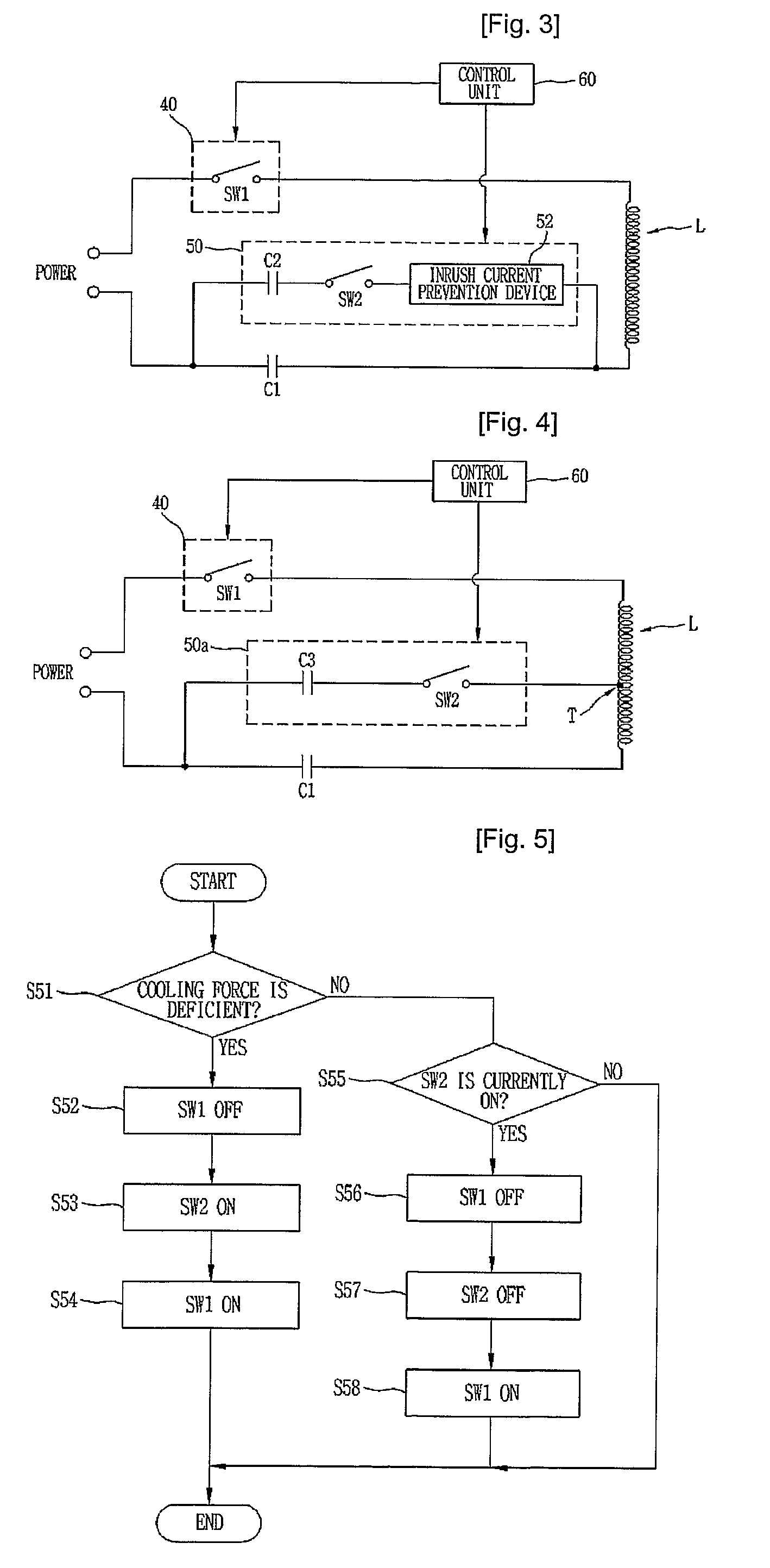
[0072]FIG. 4 is a circuit view illustrating a control apparatus for a linear compressor in accordance with the present invention.

[0073]As depicted in FIG. 4, the control apparatus for the linear compressor includes an on / off switch SW140 for receiving power and supplying power to the linear motor 10, a oil winding body L (identical to the coil winding body 14a of FIG. 2) wound in the circumferential direction of the linear compressor, a capacitor C1 connected in series to the coil winding body L, a capacitance varying unit 50a having one end connected to one end of the capacitor C1 and the other end connected to a winding tap T of the coil winding body L, the capacitance varying unit 50a being connected in parallel to the capacitor C1, and a control unit 60 for controlling the capacitance varying unit 50a to change an output of the linear compressor.

[0074]Here, the on / off switch SW140, the coil winding body L and the capacitor C1 of FIG. 4 are identical to those of FIG. 3 with the s...


PUM


Abstract

The present invention discloses a control apparatus for a linear compressor which can vary a cooling force and prevent an inrush current. The control apparatus for the linear compressor includes a coil winding body laminated on the linear compressor, a first capacitor connected in series to the coil winding body, a capacitance varying unit being formed in a parallel structure to the first capacitor, and having a capacitor switch, and a control unit for inducing an output change of the linear compressor, by varying the whole capacitance of the control apparatus by controlling the capacitor switch.

Description

[0001]This application claims priority to International application No. PCT / KR2007 / 000272 filed on Jan. 16, 2007 which claims priority to Korean Application No. 10-2006-0010264 filed Feb. 2, 2006, Korean Application No. 10-2006-0010266 filed Feb. 2, 2006, Korean Application No. 10-2006-0010267 filed Feb. 2, 2006, and Korean Application No. 10-2006-0010269 filed Feb. 2, 2006, all of which are incorporated by reference, as if fully set forth herein.TECHNICAL FIELD[0002]The present invention relates to a linear compressor, and more particularly, to a control apparatus for a linear compressor which can vary a cooling force and prevent an inrush current.BACKGROUND ART[0003]In general, a compressor is a mechanical apparatus for raising a pressure, by receiving power from a power generation apparatus such as an electric motor or turbine, and compressing the air, refrigerants or other various operation gases. The compressor has been widely used for an electric home appliance such as a refri...

Claims


Application Information

Patent Timeline
Patent Type & Authority Patents(United States)
IPC IPC(8): H02H7/08F04B35/04F04B49/06F04B49/10H02P25/06H02P25/064
CPCF04B35/04F04B35/045F04B49/06F04B49/065H02P1/44H02P25/027H02P25/06F04B2203/0401F04B2203/0402F04B2203/0404F04B2203/0408F04B2207/01F04B2207/047F04B2207/048H02P25/032H02P25/062
Inventor ROH, CHULGIKIM, JONG-KWONBAE, JUNG-WOOKKANG, HEE-DONG
Owner LG ELECTRONICS INC
Why Eureka
Try Eureka