Supercharge Your Innovation With Domain-Expert AI Agents!

Apparatus and methods for analysis and sorting of particles such as polymer beads

a particle and particle technology, applied in the field of apparatus for analysing beads and particles, can solve the problems of not being able to complete algebra in time, not being able to operate in all windows not being able to reliably or optimally operate devices in the window of opportunity of less than 1 millisecond, etc., to achieve high throughput rate and facilitate analysis of beads. , the effect of high throughput ra

Inactive Publication Date: 2011-01-11
MPM HLDG APS
View PDF36 Cites 9 Cited by
  • Summary
  • Abstract
  • Description
  • Claims
  • Application Information

AI Technical Summary

Benefits of technology

"The present invention is an apparatus for analyzing beads and particles, particularly polymer beads used in solid phase synthesis. The apparatus includes a rotatable capture body with a plurality of through-going inlets, a pressure controlling device, and a device for rotating the capture body. The beads can be fixed onto the capture body by applying a pressure drop, allowing for individual analysis and sorting. The apparatus can measure and analyze the beads' properties with high through-put rates, and can also identify and sort the beads based on their properties. The invention offers improved efficiency and accuracy compared to prior art methods."

Problems solved by technology

This poses a number of serious problem as not all measuring or analysing devices can operate within such a short “window of opportunity” for measuring and analysing bead properties.
Furthermore, the devices which can in fact operate in the “window of opportunity” of less than 1 millisecond often does not work reliably or under optimal conditions with such a short residence time of the beads.
If there is a need for sorting the beads on the basis of the measured properties, there is often not enough time to complete the algebra and very complicated mathematical calculations required to establish whether a bead is to be selected or discarded on the basis of the measurement and analysis performed.
Accordingly, time consuming mathematical calculations cannot be used in this context as a bead would have passed the sorting unit long before the result of the measuring of bead properties can be established.
Increasing the distance between the measuring section and the sorting unit often does not offer any practical solution to the problem as an increased distance also increases the risk of beads getting stuck to the wall sections, or getting stuck together, and a longer flow section furthermore contributes to variations in the velocity of individual beads—both of which factors will result in a reduced validity of the results required for a correct sorting of beads.
A further problem often encountered in purely fluid dynamic based bead manipulation methods is that the flow of beads cannot be interrupted on demand without such an interruption causing a considerable shutdown period followed by often laborious and time-consuming start up procedures.
During the operation of a purely fluid based bead sorter, such as e.g. the COPAS bead sorter supplied by Harvard Bioscience, a number of difficulties regarding fluid handling of particles such as e.g. polymer beads are experienced.
This is time-consuming and inefficient as it requires beads to be measured and analysed more than once.
This places very high demands on sensors, data handling equipment, and the fluid handling components of the sorting unit.
In cases where advanced bead analysis, such as resolving the three dimensional structure of spatially encoded microparticles must be carried out at a high through-put rate, high flow velocities and corresponding low residence times in the flow cell poses an even greater challenge for the equipment as the data handling is much more complex compared to conventional bead sorters in which a more simple analysis, such as bead size or total fluorescence, is measured.

Method used


Image

  • Apparatus and methods for analysis and sorting of particles such as polymer beads
  • Apparatus and methods for analysis and sorting of particles such as polymer beads
  • Apparatus and methods for analysis and sorting of particles such as polymer beads

Examples


example 1

Handling and Imaging of Spatially Encoded Polymer Beads

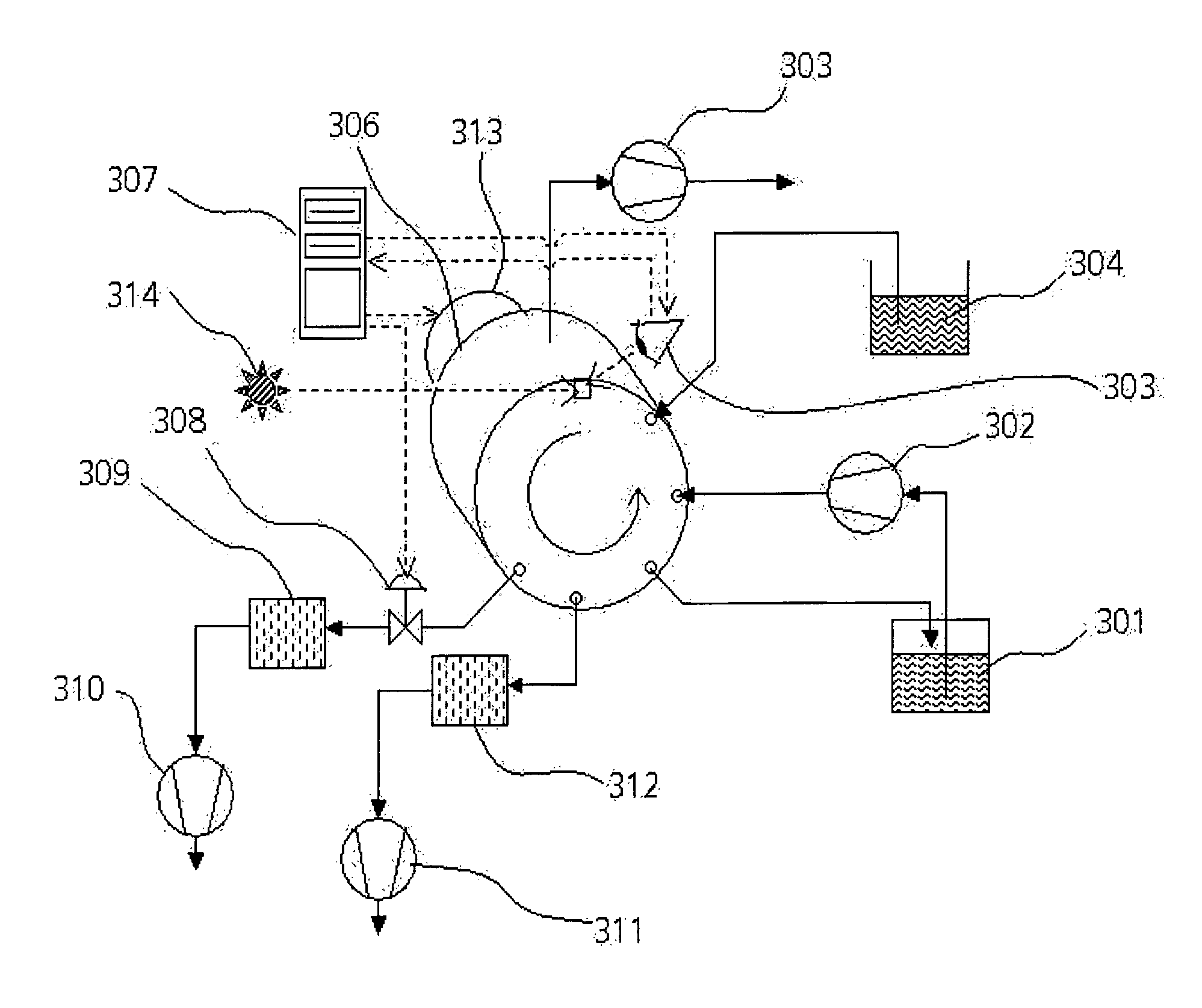
[0617]A bead sorting apparatus with auxiliaries for controlling the bead sorting, for imaging the beads, and for supplying vacuum was constructed comprising (numbers referring FIG. 7)[0618]a rotating vacuum container comprising[0619]a 100 mm diameter POM capture disc with 100 equidistant 0.2 mm diameter capture holes, arranged along an 80 mm diameter circular track running 10 mm from the edge of the capture disc, the capture disc being positioned with its planar surfaces vertical,[0620]a 100 mm outer diameter POM capture disc holder for holding the capture disc and for containing the vacuum inside the vacuum container, and[0621]a 5 mm outer diameter and 3 mm inner diameter stainless steel shaft with a hole therein for applying a vacuum,[0622]a vacuum container housing comprising[0623]a stainless steel cylinder (306) of inner diameter 10.2 mm surrounding the vacuum container,[0624]a stainless steel circular back plate with a cent...

example 2

Upscaled Handling and Imaging of Spatially Encoded Polymer Beads

[0661]The bead handling apparatus and auxiliaries described in Example 1 were operated with the following operation parameters:

[0662]The first gear pump was running at 2500 rpm.

[0663]The second gear pump was running at 40% of maximum rotational speed.

[0664]The first pulse generator was running in continuous single pulse mode with 0.08 seconds between pulses and a pulse width 0.5 milliseconds.

[0665]The bead feeding syringe was mounted on a syringe pump set to run in continuous withdrawal / infusion mode with volume setting 0.1 milliliter and rate setting 1.0 ml / min.

[0666]It was noted that the actual volume of infused bead dispersion per withdrawal / infusion cycle was substantially less than the nominal value of 0.1 milliliter due to the combined mechanical bias of the syringe mounting and of the flexible plastic syringe itself.

[0667]The second pulse generator was running in delayed triggered pulse mode with a delay of 0.1 s...

example 3

High Focal Depth Imaging of Spatially Encoded Beads

[0681]The bead handling apparatus auxiliaries described in example 1 was modified in the following way: One of the 0.8× magnification, 6 mm aperture microscopes was replaced by a 10× magnification, 1.5 mm aperture microscope.

[0682]The bead handling apparatus described in example 1 and the modified auxiliaries was operated in the same way as described in example 1 with the exception that only images from the camera equipped with the low aperture optics were recorded.

[0683]Four images from the resulting image sequence are given in FIG. 15 and show a marked increase in focal depth compared to the images from example 1. It is also clear that the decrease in aperture has led to darker images, as one would expect. Indeed, fluorescence imaging with the use of low aperture optics and exposure times in the millisecond range is a challenging task. However, the dot code clearly appears in the images in FIG. 15. It can be concluded that the use...


PUM

PropertyMeasurementUnit
velocitiesaaaaaaaaaa
residence timeaaaaaaaaaa
flow velocityaaaaaaaaaa

Abstract

The present invention relates to an apparatus for analysing beads and particles, such as polymer beads used e.g. for solid phase synthesis. The apparatus comprises a) a vacuum container comprising at least one planar capture body capable of rotating around a central axis, wherein said capture body comprises a plurality of through-going inlets, and wherein the diameter of each inlet is smaller than the average diameter of the beads to be measured and / or analysed and / or sorted, b) a pressure controlling device capable of controlling the pressure in the vacuum container, c) a device for rotating the vacuum container around the axis of the capture body, and d) a device for measuring at least one property of at least one bead, the apparatus further comprising a capture body support, supporting the capture body, and a vacuum container housing.

Description

[0001]All patent and non-patent references cited herein are incorporated in their entirety. This application is a non-provisional of U.S. provisional application Ser. No. 60 / 535,522 filed 12 Jan. 2004, which is hereby incorporated by reference in its entirety.FIELD OF INVENTION[0002]The present invention relates to an apparatus for analysing beads and particles, such as polymer beads used e.g. for solid phase synthesis. The apparatus in one embodiment comprises a rotatable, circular disc comprising a plurality of through-going inlets, wherein an individual bead from a composition comprising different beads can be fixed to the disc at the end-position of a through-going inlet by applying a pressure drop over said disc comprising said through-going inlets. The pressure drop results in beads being sucked (i.e. detachably fixed) onto the disc on top of the through-going inlets.[0003]When the disc is rotated the beads are transferred from the position where they initially became attached...

Claims


Application Information

Patent Timeline
Patent Type & Authority Patents(United States)
IPC IPC(8): G01J3/44B01J19/00C40B70/00G01N15/14G01N21/03G01N21/64G01N35/00
CPCG01N21/645B01J2219/00468B01J2219/005B01J2219/00551C40B70/00G01N2015/149G01N2021/6417G01N2035/00574G01N15/149
Inventor CHRISTENSEN, SOEREN FLYGENRINGJOHANNSEN, IB
Owner MPM HLDG APS
Features
  • R&D
  • Intellectual Property
  • Life Sciences
  • Materials
  • Tech Scout
  • Unparalleled Data Quality
  • Higher Quality Content
  • 60% Fewer Hallucinations
Learn More