Arrangement for supplying a medium into an exhaust gas conduit in an internal combustion engine

a technology of exhaust gas conduit and medium, which is applied in the direction of lighting and heating apparatus, combustion types, separation processes, etc., can solve the problems of reducing the temperature on the first wall surface of the exhaust line, vaporising the medium, etc., and achieves the effect of reducing the cooling effect of the environment on the inside wall surface, and reducing the temperature of the first wall surfa

Inactive Publication Date: 2011-02-01
SCANIA CV AB
View PDF21 Cites 44 Cited by
  • Summary
  • Abstract
  • Description
  • Claims
  • Application Information

AI Technical Summary

Benefits of technology

[0008]According to a preferred embodiment of the present invention, said element is a wall element applied in a spiral exhaust line and dividing a portion of the exhaust line into a first exhaust passage and a second exhaust passage. A spiral exhaust line is compact and heat transfer between adjoining radial portions of the exhaust line is not complicated. However, the sidewalls of a spiral exhaust line are usually in contact with ambient air. With a wall element as above, the first exhaust passage can be provided with sidewall surfaces heated by surrounding exhaust gases. The first passage can therefore be so arranged as to be completely surrounded by inside wall surfaces which are heated by surrounding exhaust gases.
[0009]According to an alternative embodiment of the present invention, the element constitutes an integral part of the exhaust line and said means comprises a thermally insulating material applied between the first wall surface and an environment. In this case the element is shaped like the exhaust line but may be made of a material with considerably higher thermally insulating properties than the exhaust line elsewhere. Alternatively, a suitable insulating material of appropriate thickness may be applied round the outside surface of the element. With such a thermally insulating material, the cooling action of the environment on the inside wall surface can be substantially eliminated. The inside wall surface of the element will then only be heated by the exhaust gases flowing through the first exhaust passage, but this heat supply is usually amply sufficient to cause the medium in liquid form which reaches the inside wall surface to vaporise, since the cooling action of the environment on the first wall surface has been eliminated.
[0010]According to another preferred embodiment of the present invention, the dosing device comprises a spray nozzle by which the medium is sprayed into said first exhaust passage. A spray nozzle results in very fine division of the liquid medium being sprayed into the tubular element. The result is rapid and effective vaporisation of the medium when it mixes with the exhaust gases flowing through the tubular element. With advantage, the medium is a urea solution and the exhaust line contains a catalyst. In particular, when the technique known as SCR (selective catalytic reduction) is used, a urea solution can be used for providing ammonia, which is a necessary substance for effecting a chemical reaction whereby the nitrogen oxides in the exhaust gases are reduced to nitrogen gas and water vapour. A urea solution is easy to handle and store because it is both relatively odourless and non-toxic. Supplying the urea solution in well-defined doses enables the diesel engine's discharge of nitrogen oxides to be considerably reduced. The present invention makes it possible for an optimum supply of urea to be provided, with the result that all the urea solution supplied is certain to vaporise. It is also possible with the present invention to supply other media than urea to the exhaust line.
[0011]According to another preferred embodiment of the present invention, the inside wall surface of the element comprises at least one region with an uneven surface. The result is that in that region the tubular element has a larger inside wall surface than in the case of an even surface. An uneven wall surface detains liquid urea solution until it vaporises. The inside wall surface of the element may comprise at least one recess which has an extent in a direction substantially perpendicular to the direction of flow of the exhaust gases in the first exhaust passage. The liquid medium is thus effectively detained in the recess until it vaporises. Such recesses at suitable locations make it possible for the element to be of reduced length.
[0012]According to another preferred embodiment of the present invention, said nozzle comprises a plurality of radial apertures which lead the medium in the first exhaust passage in directions substantially perpendicular to the main direction of flow of the exhaust gases in the first exhaust passage. The liquid medium thus meets the exhaust flow in such a way that a large proportion of the medium is entrained by the flowing exhaust gases and vaporises before it reaches an inside wall surface of the first exhaust passage. Said nozzle may be applied in a curved first exhaust passage situated in a portion of a spiral exhaust line which extends about a central axis, whereby the positioning of the nozzle apertures is such that the medium is supplied in directions which predominantly lead the medium radially inwards towards said central axis in the curved first exhaust passage. A liquid medium which is heavier than the exhaust gases and is flung radially outwards by centrifugal force in a curved exhaust passage may well result in a relatively large proportion of the medium supplied accumulating on a radially outside wall surface of the exhaust passage. This entails a risk of the temperature of this limited surface being lowered to a level such that the accumulated medium does not vaporise quickly enough. To counteract such accumulation, the medium is therefore distributed by the nozzle predominantly radially inwards so that such accumulation of the medium on a radially outside wall surface of the exhaust passage is prevented.
[0013]According to another preferred embodiment of the present invention, the first exhaust passage is bounded in an axial direction relative to said central axis by two wall elements situated at a distance from one another, and in a radial direction relative to said central axis by an outer wall element and an inner wall element, whereby the nozzle is adapted to supplying the medium in at least one direction towards each of the axial wall elements and the radial inner wall element, but not in any direction towards the radial outer wall element. Suitable distribution of the nozzle apertures enables the medium to be supplied substantially uniformly to the axial wall elements and the radial inner wall element. The radial outer wall element may also receive a corresponding amount of the medium when the liquid medium supplied is led radially outwards by centrifugal force in the curved exhaust passage. With advantage, the nozzle is fitted in the first exhaust passage at a position situated closer to the radial outer wall element than the radial inner wall element. As the medium is substantially supplied more or less radially inwards in the spiral exhaust passage, the distance between the nozzle apertures and their intended liquid contact areas on inside surfaces of the exhaust passage is thereby increased. Increasing this distance enables a larger proportion of the amount of medium supplied to be entrained by and vaporised in the exhaust flow before it reaches an inside surface of the exhaust passage.

Problems solved by technology

Problems with vaporising the medium usually only arise when medium in liquid form reaches the inside wall surface and the inside wall surface is at too low a temperature to immediately vaporise the medium.
High dosage of the medium may also lower the temperature on the first wall surface of the exhaust line considerably, since vaporising the medium consumes a good deal of thermal energy.

Method used


Image

  • Arrangement for supplying a medium into an exhaust gas conduit in an internal combustion engine
  • Arrangement for supplying a medium into an exhaust gas conduit in an internal combustion engine
  • Arrangement for supplying a medium into an exhaust gas conduit in an internal combustion engine

Examples


Embodiment Construction

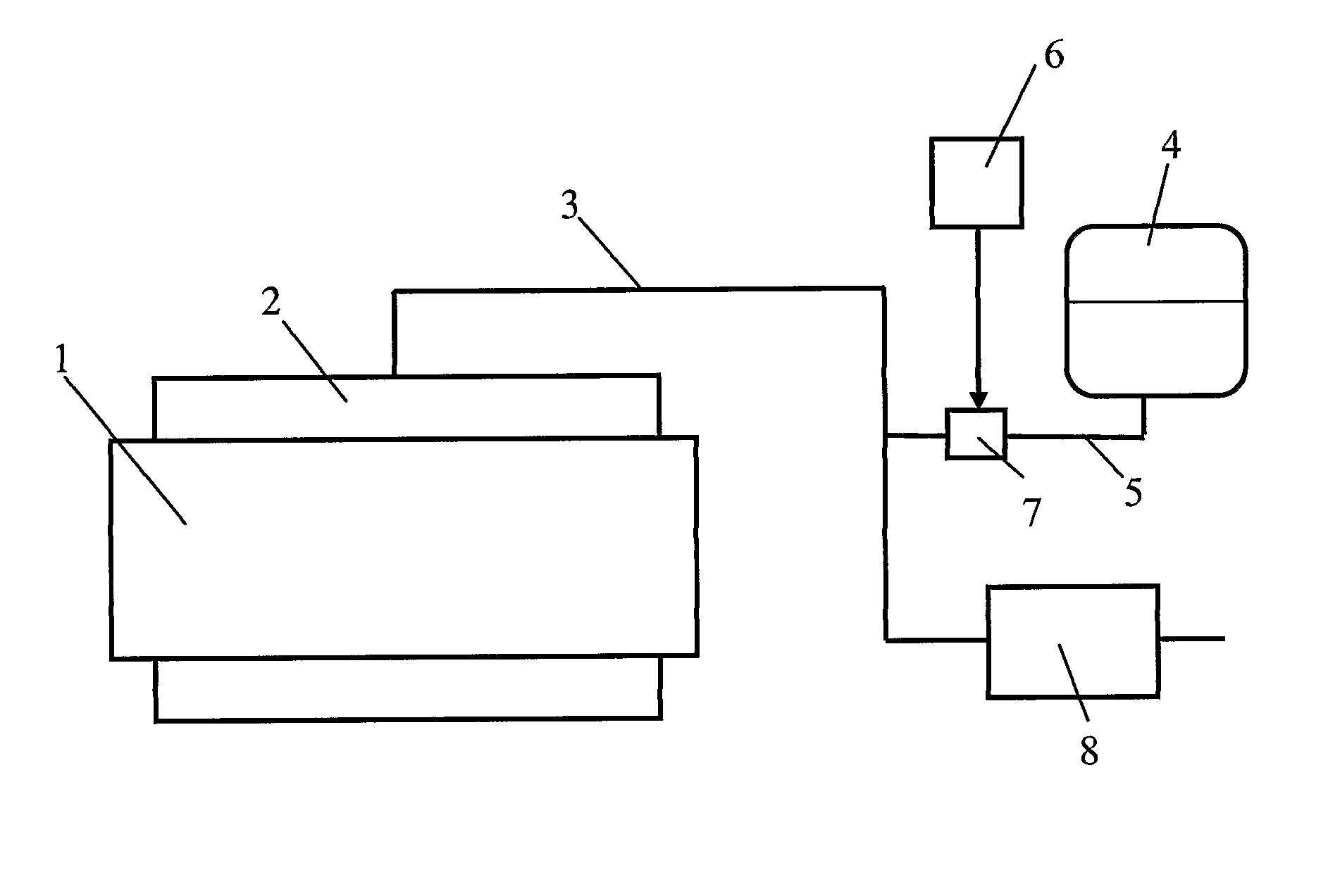
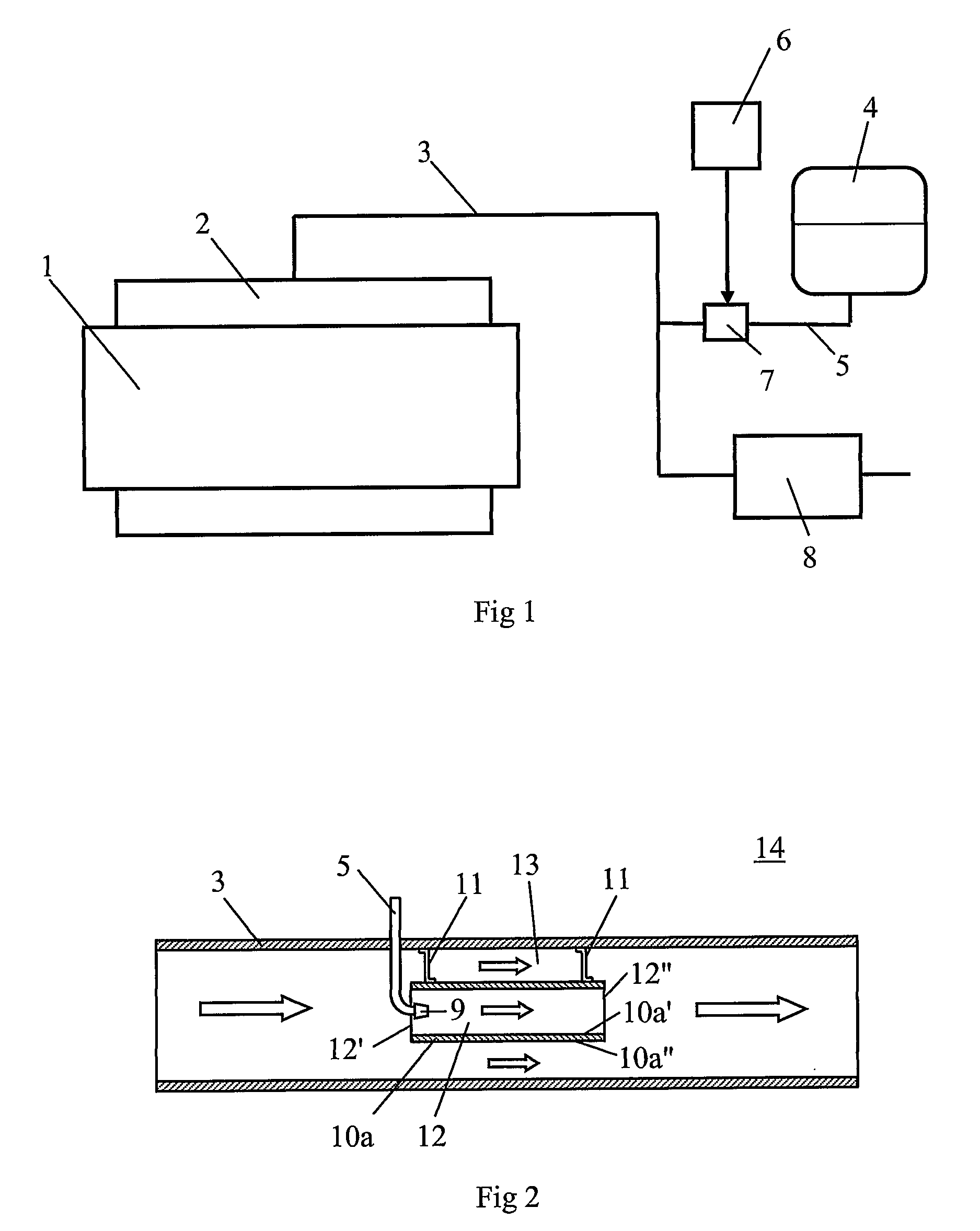
[0025]FIG. 1 depicts a combustion engine in the form of a diesel engine 1. The diesel engine 1 may for example be intended to power a heavy vehicle. The exhaust gases from the cylinders of the diesel engine 1 are led via an exhaust manifold 2 to an exhaust line 3. In this case the exhaust line 3 is provided with an arrangement which effects catalytic exhaust cleaning according to the method known as SCR (selective catalytic reduction). This method entails a urea solution being added to the exhaust gases in the diesel engine's exhaust line 3. The urea solution is stored in a tank 4 and is led via a line 5 to the exhaust line 3. A control unit 6, which may be a computer unit with suitable software, controls the supply of the urea solution which is led to the exhaust line 3 by activating a pump 7. The control unit 6 may use information concerning current fuel consumption and the temperature of the exhaust gases to calculate the amount of urea solution which needs to be added for optimu...


PUM

PropertyMeasurementUnit
diameteraaaaaaaaaa
diameteraaaaaaaaaa
degree of heatingaaaaaaaaaa

Abstract

An arrangement for supplying a medium to an exhaust line of a combustion engine. The arrangement comprises a first exhaust passage defined by at least a first wall surface of an element, and a dosing device supplying the medium to the first exhaust passage. The arrangement is adapted to maintaining a degree of heating of the first wall surface so that the latter will be at a higher temperature than the medium's vaporization point when the liquid medium is supplied in the first exhaust passage. Therefore, even the medium which reaches the first wall surface will vaporize in the first exhaust passage.

Description

CROSS REFERENCE TO RELATED APPLICATION[0001]The present application is a 35 U.S.C. §§371 national phase conversion of PCT / SE2005 / 000584, filed 22 Apr. 2005, which claims priority of Swedish Application No. 0401990-7 filed 6 Aug. 2004. The PCT International Application was published in the English language.BACKGROUND TO THE INVENTION, AND STATE OF THE ART[0002]The invention relates to an arrangement for supplying a medium to an exhaust line of a combustion engine and for vaporizing the medium in the exhaust line.[0003]A technique known as SCR (selective catalytic reduction) is used for reducing discharges of nitrogen oxides from diesel engines. This technique involves adding a solution of urea in a specified dose to the exhaust gases in the exhaust line of a diesel engine. The urea solution may be sprayed into the exhaust line in such a way that it is finely divided, after which the urea solution in contact with the hot exhaust gases vaporises and ammonia is formed. The mixture of am...

Claims


Application Information

Patent Timeline
Patent Type & Authority Patents(United States)
IPC IPC(8): F01N3/00F23D11/10B01D53/56F23D11/40F23D14/62B05B7/06B05B7/08B05B7/04B05B1/14B05B1/20B05B1/18F01NF01N1/08F01N1/12F01N3/20F01N13/02
CPCB01F3/04049B01F5/0644F01N1/084F01N1/12F01N13/0097F01N3/2066F01N2470/24F01N2610/02F01N2610/102Y02T10/24Y02T10/12B01F23/2132B01F25/4323F01N3/206
Inventor KUNKEL, CHRISTIANWESTERBERG, BJORNHAGGKVIST, ANDERS
Owner SCANIA CV AB
Why Eureka
Try Eureka