

Production method of honeycomb filter and honeycomb filter
a production method and technology of honeycomb filter, applied in the direction of filtration separation, machine/engine, separation process, etc., can solve the problems of reducing engine power, increasing pressure loss, and reducing capture performance, so as to avoid clogging with a plugging material
- Summary
- Abstract
- Description
- Claims
- Application Information
AI Technical Summary
Benefits of technology
Problems solved by technology
Method used
Image

Examples
example 1
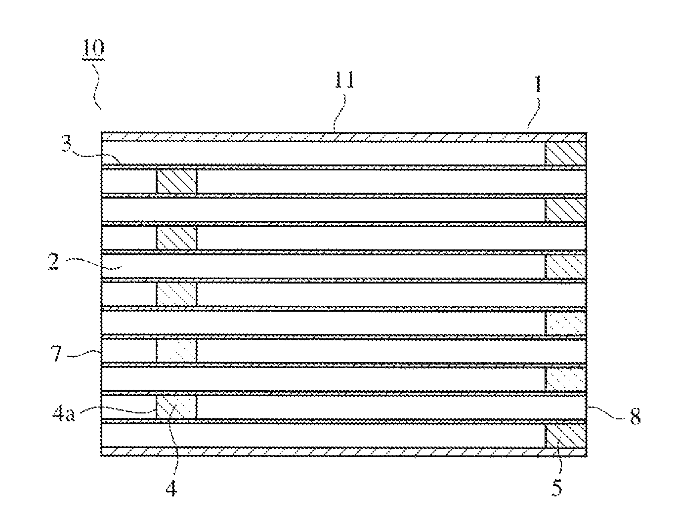
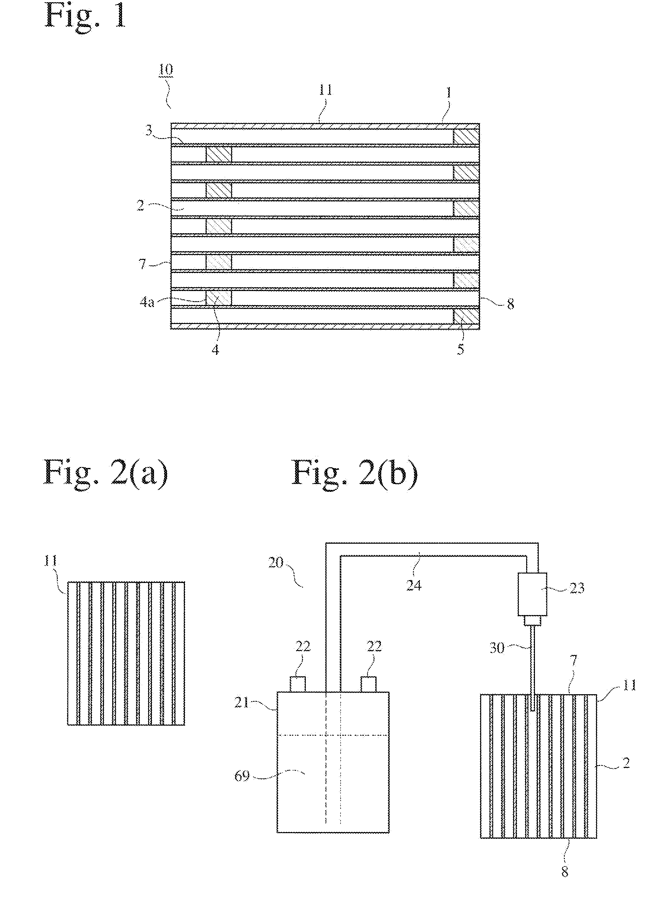
[0144]Kaolin powder, talc powder, silica powder, aluminum hydroxide powder and alumina powder were mixed at proportions of 50% by mass of SiO2, 35% by mass of Al2O3, and 15% by mass of MgO, and methylcellulose and hydroxypropylmethylcellulose as binders, and graphite as a lubricant / pore-forming agent were added. After fully dry-blending, a predetermined amount of water was added to conduct sufficient blending, thereby producing a plasticized, moldable ceramic material. The moldable material was extruded through an extrusion die, and cut to form an extrudate having a honeycomb shape. This extrudate was dried and sintered to provide a cordierite honeycomb structure 11 of 280 mm in outer diameter and 310 mm in length shown in FIG. 2(a), whose cell walls had a thickness of 0.3 mm, a porosity of 65%, an average pore size of 20 μm, and a pitch of 1.5 mm.
[0145]As shown in FIG. 2(b), the honeycomb structure 11 was placed near a plugging-material-supplying apparatus 20 comprising a plugging ...
example 2
[0148]Like in Example 1, a honeycomb structure 11 was placed near the plugging-material-supplying apparatus 20 such that the flow path direction was substantially aligned with the gravity direction. The tubular member for supplying the plugging material was made of stainless steel and had a circular cross section having a length of 100 mm, an outer diameter of 1.1 mm and an inner diameter of 0.8 mm. A plugging ceramic material was produced by blending 100 parts by mass of cordierite powder an average particle size of 25 μm and a maximum particle size of 500 μm with 30 parts by mass of water, and filled in the plugging material tank 21.
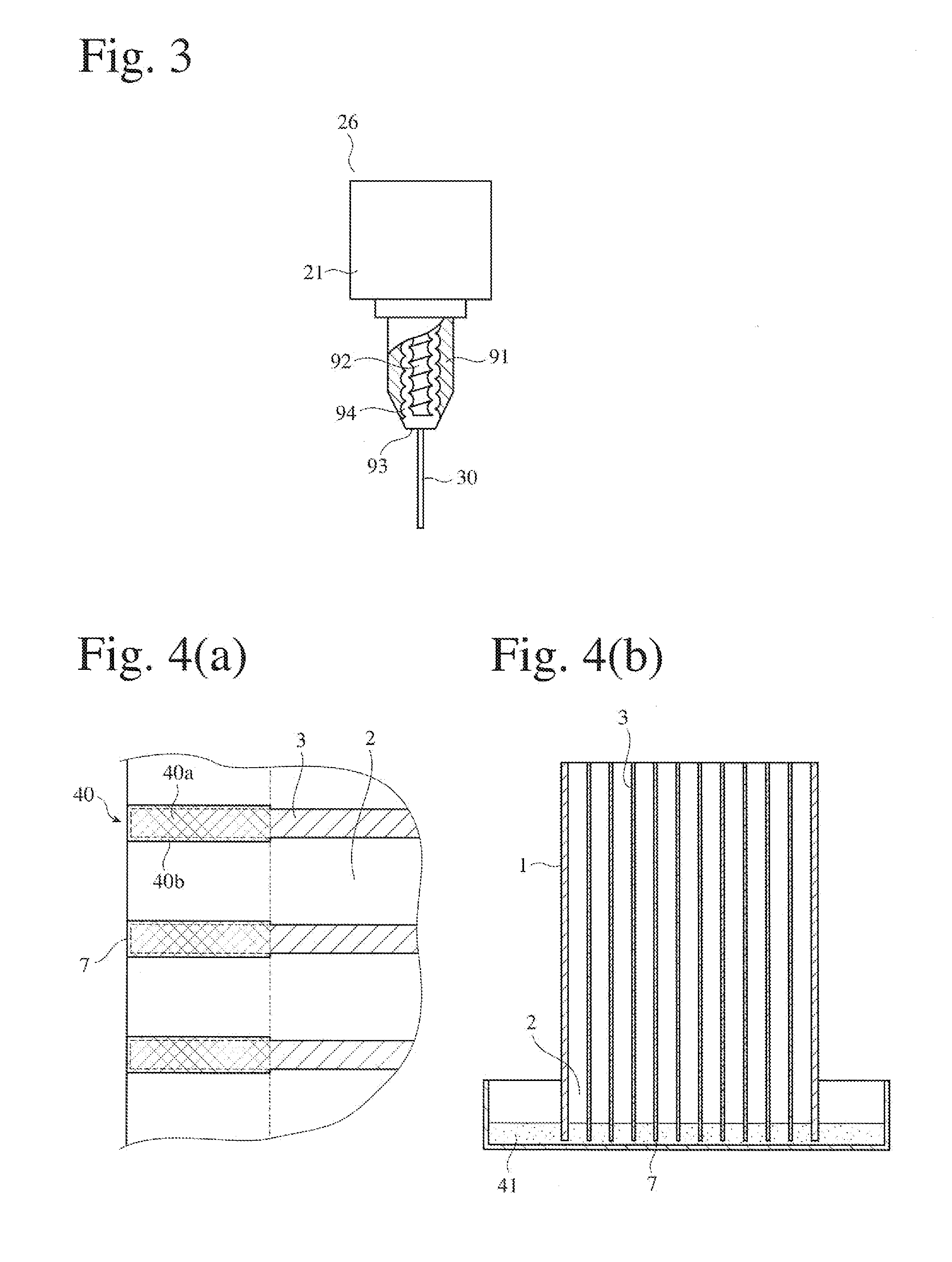
[0149]The tubular member 30 was inserted into a flow path to be plugged to a position of 30 mm from the end surface 7 of the honeycomb structure 11, and the plugging material tank 21 was pressurized by air supplied through an air-supplying valve 22 to inject a predetermined amount of the plugging material into the flow path through the tubular member f...
example 3
[0151]Like in Example 1, an end surface of a honeycomb structure 11 was placed in a plugging-material-supplying apparatus 20 such that the flow path direction was substantially aligned with the gravity direction. A tubular member for supplying the plugging material was made of stainless steel and had a circular cross section having a length of 100 mm, an outer diameter of 1.1 mm and an inner diameter of 0.8 mm. A plugging ceramic material was produced by blending 100 parts by mass of cordierite powder an average particle size of 30 μm and a maximum particle size of 700 μm, with 30 parts by mass of water and 2 parts by mass of ammonium polycarbonate as an agglomeration-preventing agent, and filled in the plugging material tank 21.
[0152]The tubular member 30 was inserted into a flow path to be plugged to a position of 20 mm from the end surface 7 of the honeycomb structure 11, and the plugging material tank 21 was pressurized by air supplied through an air-supplying valve 22 to inject...
PUM
| Property | Measurement | Unit |
|---|---|---|
| particle size | aaaaa | aaaaa |
| porosity | aaaaa | aaaaa |
| porosity | aaaaa | aaaaa |
Abstract
Description
Claims
Application Information