Device to move an object back and forth

a technology of moving objects and objects, applied in the direction of cosmonautic vehicles, machines/engines, transportation and packaging, etc., can solve the problems of debris being particularly dangerous to equatorial satellites, ipd could have taken several months or longer to slowly deorbit the satellite, and debris will remain a hazard for centuries to com

Active Publication Date: 2011-03-08
FIALA HARVEY EMANUEL +2
View PDF7 Cites 12 Cited by
  • Summary
  • Abstract
  • Description
  • Claims
  • Application Information

AI Technical Summary

Benefits of technology

[0024]Aircraft in level flight could use inertial propulsion to save on fuel costs to the extent that generating electrical energy for inertial propulsion would be more efficient than developing thrust using jet engines. Because objects have their normal weight during normal flight, MMT could be used to increase the flight speed during normal flight and reduce the speed during landing. This would be helpful for takeoffs and landings on short runways and to reduce noise to below legal limits during takeoffs and landings where this is critical (for example, the John Wayne Airport in Orange County, California). Dirigibles could be powered by MMT. Submarines could move in total silence with no external moving parts.
[0030]For satellite station-keeping, a special space-qualified VMT IPD could be designed using magnetic bearings for the rotors and make the design completely free of any wear on the moving parts. A space qualified VMT IPD could probably be developed for less than the cost of conventional station-keeping hardware.

Problems solved by technology

For a fraction of that cost, a low-performance IPD could have taken several months or longer to slowly deorbit the satellite.
However, it might require that amount of money to originally develop a space-rated VMT-IPD.
This debris will remain a hazard for centuries to come.
This debris is especially dangerous to equatorial satellites in that it is in a polar orbit and can hit a satellite broadside and unexpectedly.

Method used


Image

  • Device to move an object back and forth
  • Device to move an object back and forth
  • Device to move an object back and forth

Examples


Embodiment Construction

[0032]Since inertial propulsion is a new field and there are so many possible configurations, many different configurations have been included in this application. For learning the principles involved, the preferred embodiments are those depicted in FIGS. 1, 20, and 48. For HMT the preferred embodiment is shown in FIG. 10 (a) since all four rotors are driven by the same motor and automatically have the same angular velocity, thus eliminating any rotor speed control problems. For the sake of simplicity, for VMT the preferred embodiments are those shown in FIGS. 22 and 24, insofar as all torques about the vertical axis are cancelled out.

LIST OF DRAWINGS

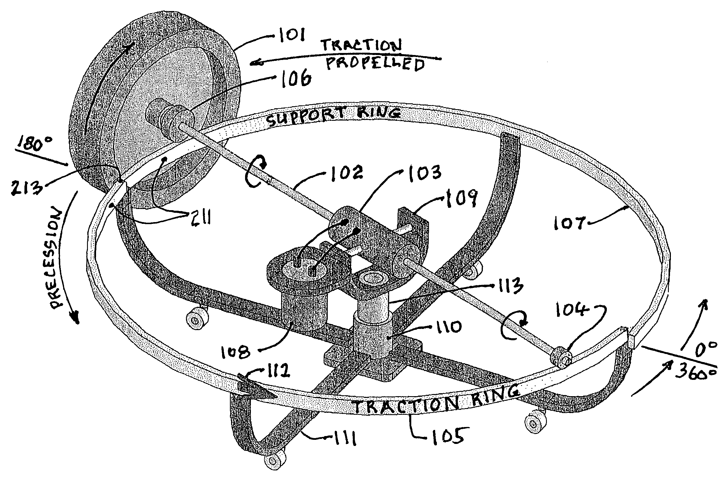
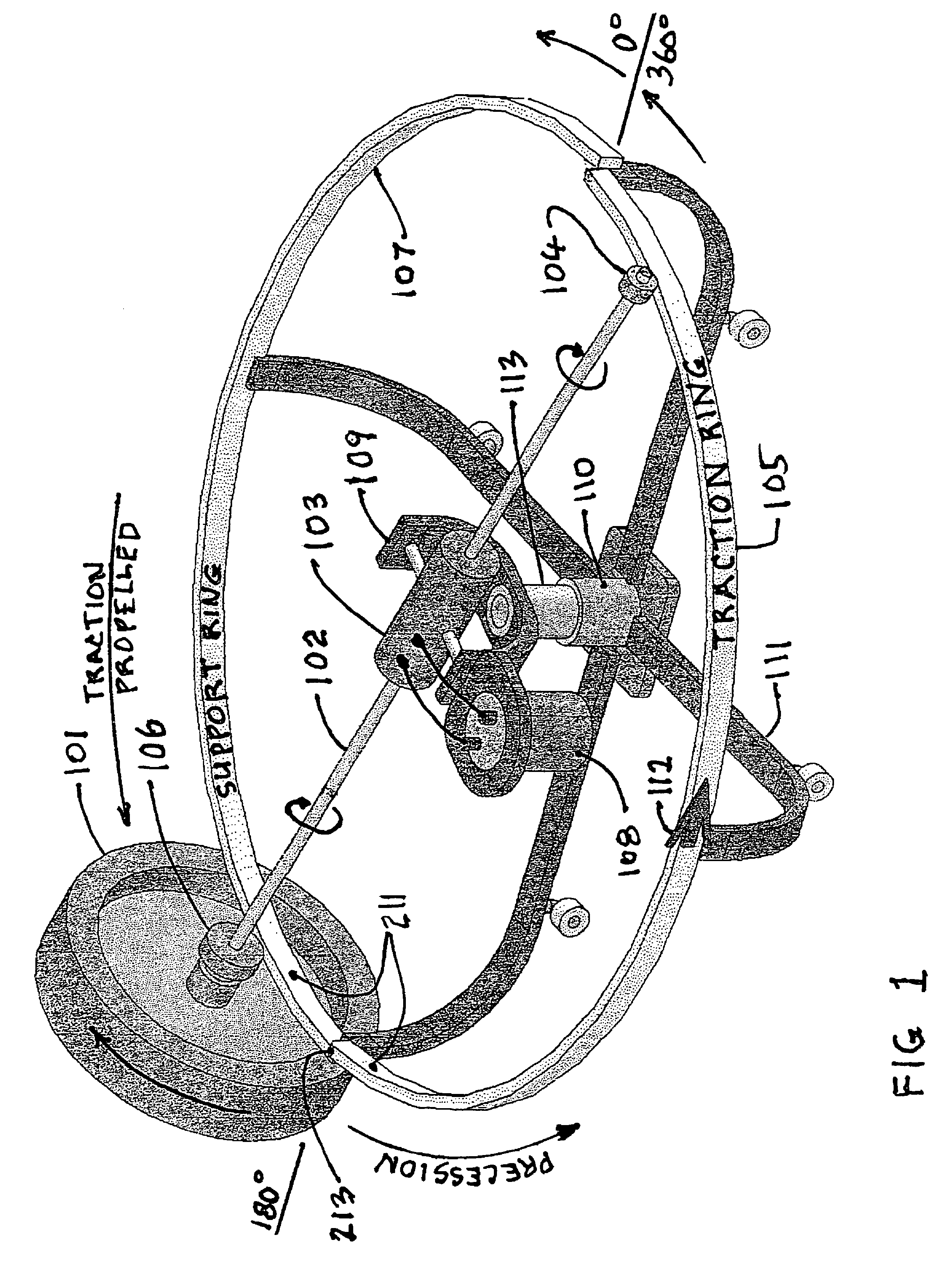
[0033]FIG. 1: Simplest One-Rotor HMT IPD

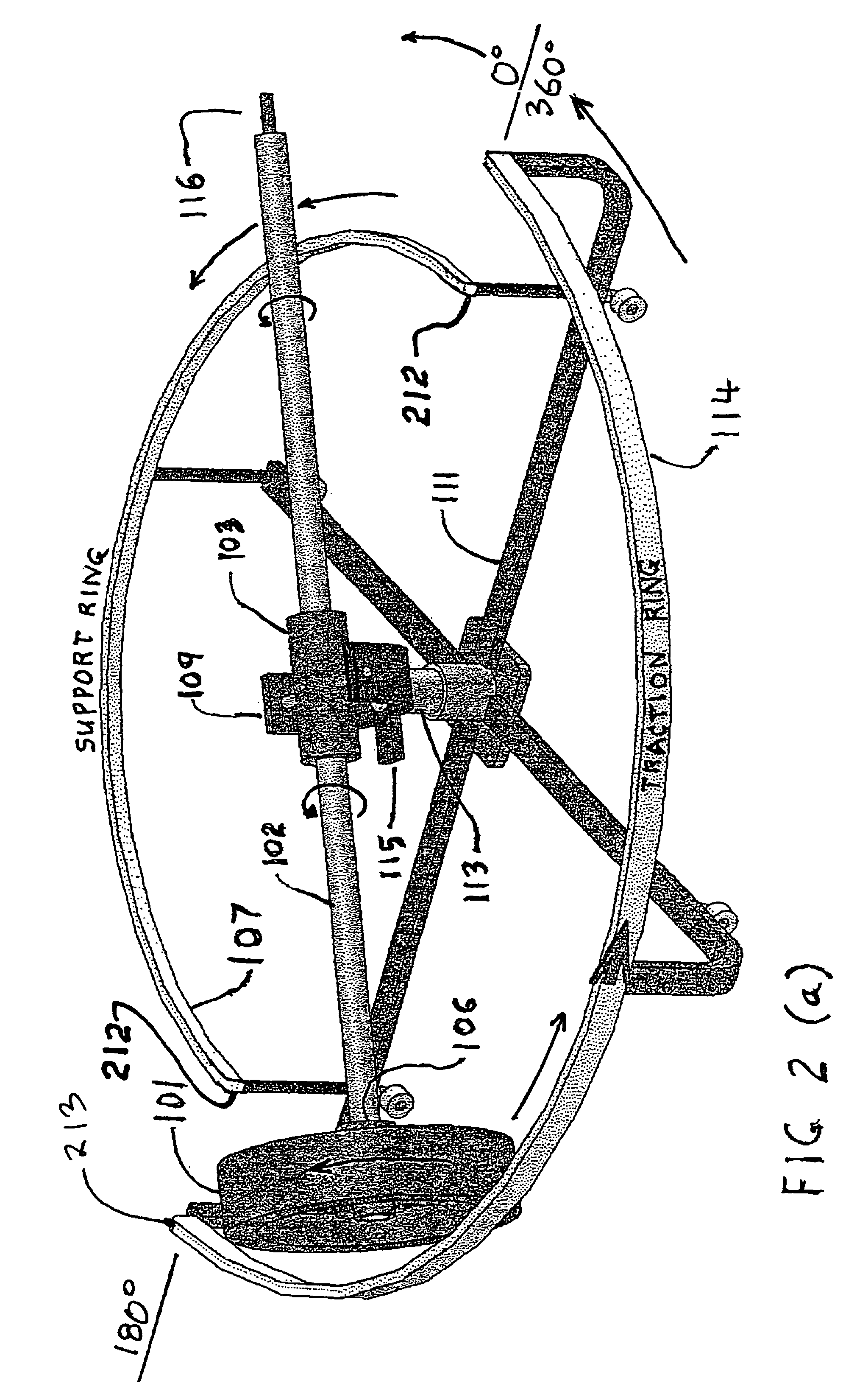
[0034]FIG. 2 (a): Alternate One-Rotor HMT Embodiment with Traction Ring Outside Rotor

[0035]FIG. 2 (b): Alternate HMT Embodiment with V-Groove Traction Ring

[0036]FIG. 3: Two Deck, Two Rotor HMT Embodiment

[0037]FIG. 4: Alternate HMT with Traction Ring Outside Rotor

[0038]FIG. 5: Two One-Rotor HMT Dec...


PUM


Abstract

Disclosed herein are two separate processes that do not require a propellant and do not produce an equal and opposite reaction against any external form of matter in the Local Inertial Reference Frame and do not violate Newton's Laws in the Universal Reference Frame. The first process produces horizontal motion, relies on the earth's gravitational field as an external force, and has been successfully tested. The second process produces vertical motion and relies only on the aether. It has been successfully tested considering the effect of the earth's gravity. Due to the law of conservation of angular momentum, the first process is normally considered not possible, but with the proper use of an external field (for example, gravity) and the phenomenon of precession, it becomes possible. A clear distinction is made between a simple rotor and a gyroscope which is a far more complex device.

Description

INTRODUCTION[0001]Inertial propulsion is a largely undeveloped field. Inertial propulsion is defined as propelling a vehicle without the use of a propellant such as rocket fuel or ions, or by the application of an obvious external force. In short, inertial propulsion is propellantless propulsion.[0002]After consulting with prominent physicists, based on current definitions, the earth's gravity is definitely considered an external field (and force). If a one pound object is sitting on a table, the gravitational field causes it to exert a one pound force on the table and to keep the object from falling the table responds by exerting an equal and opposite upward directed force. Contemporary thinking is largely that because the gravitational field is by definition exactly perpendicular to the horizontal, it can not be used to cause an object to move horizontally. This has been true for all the approaches that have been tried in the past, but that does not prove it cannot be done. It jus...

Claims


Application Information

Patent Timeline
Patent Type & Authority Patents(United States)
IPC IPC(8): B64G1/40
CPCB64G1/285B64G1/409F03G3/08F03G7/10F03G7/115F03G7/135F03G7/104
Inventor FIALA, HARVEY EMANUELFIALA, JOHN EMILFIALA, JOHN-ARTHUR
Owner FIALA HARVEY EMANUEL
Why Eureka
Try Eureka