Boundary acoustic wave device and method for manufacturing the same

a technology of acoustic waves and electrode layers, applied in piezoelectric/electrostrictive transducers, generators/motors, transducers, etc., can solve the problems of low electric power resistance of the boundary acoustic wave device, unmet significant demand, and the laminated ti layer above and below the electrode layer made of au that does not have sufficient electric power resistance. achieve the effect of enhanced electric power resistance and low loss

Active Publication Date: 2011-03-08
MURATA MFG CO LTD
View PDF8 Cites 3 Cited by
  • Summary
  • Abstract
  • Description
  • Claims
  • Application Information

AI Technical Summary

Benefits of technology

To overcome the problems described above, preferred embodiments of the present invention provide a boundary acoustic wave device having low loss in which electric power resistance is enhanced, and a method for manufacturing the device.
A boundary acoustic wave device according to a preferred embodiment of the present invention includes an electrode film disposed at a boundary between a piezoelectric substance and a dielectric substance, the electrode film preferably being one of an Au alloy electrode film including Cu at a ratio of about 0.01% to about 4.8% by weight, an Au alloy electrode film including Pd at a ratio of about 0.01% to about 20.0% by weight, and an Au alloy electrode film including Ni at a ratio of about 0.01% to about 10.5% by weight, for example. As shown using experimental examples which will be described below, it is possible to enhance the electric power resistance of the boundary acoustic wave device without degrading an insertion loss. Consequently, a boundary acoustic wave device having excellent electric power resistance and reliability can be provided.
A method for manufacturing a boundary acoustic wave device according to a preferred embodiment of the present invention includes a step of depositing an Au alloy film on a piezoelectric substance by a DC sputtering method, a RF sputtering method, or an electron beam evaporation method, for example. In this step, any one of an Au alloy including Cu at a ratio of about 0.01% to about 4.8% by weight, an Au alloy including Pd at a ratio of about 0.01% to about 20.0% by weight, and an Au alloy including Ni at a ratio of about 0.01% to about 10.5% by weight or two elemental metals prepared at a ratio corresponding to any one of the Au alloy compositions are used as a raw material, i.e., a target in the sputtering method or an evaporation source in the electron beam evaporation method. Therefore, in the Au alloy electrode film, the content of Cu, Pd, or Ni is within one of the ranges described above. Thus, a boundary acoustic wave device according to a preferred embodiment of the present invention having excellent electric power resistance can be provided. In addition, a boundary acoustic wave device according to a preferred embodiment of the present invention can be easily and securely manufactured only by controlling the composition of an Au alloy prepared as a target in the sputtering method or an evaporation source in the electron beam evaporation method or only by controlling the ratio of two elemental metals.
As disclosed in U.S. Patent Application Publication No. 2008 / 0290968, one of the inventors of the present patent application previously developed a method of forming an Au—Ni alloy layer by forming a laminated film made of Ti / Ni / Au / Ni / Ti on a piezoelectric substance and then diffusing Ni into Au by heating. In U.S. Patent Application Publication No. 2008 / 0290968, Ni is diffused into Au by heating, thereby enhancing the hardness of an electrode film. The method described in U.S. Patent Application Publication No. 2008 / 0290968 is capable of easily controlling the composition as compared to using an alloy from the beginning. However, it is necessary to precisely control a heating process in order to control diffusion in order to obtain an optimum composition. In addition, heat and electric energy are applied, and thus, Ni diffusion further proceeds, thereby possibly deviating from an optimum composition.
In contrast, in the manufacturing method according to various preferred embodiments of the present invention, the Au alloy film is formed by a DC sputtering method, a RF sputtering method, or an electron beam evaporation method, for example, using an Au alloy as a raw material from the beginning. Therefore, the Au alloy film with a target composition can be easily and securely formed without deviating from an optimum composition.

Problems solved by technology

Thus, a boundary acoustic wave device has a problem of low electric power resistance as compared to surface acoustic wave devices.
However, the structure in which the Ti layers are laminated above and below the electrode layer made of Au does not have sufficient electric power resistance, and further improvements in the electric power resistance have been required.
Furthermore, in a boundary acoustic wave device, there has been an unmet significant demand for not only enhancing electric power resistance but also decreasing insertion loss.

Method used


Image

  • Boundary acoustic wave device and method for manufacturing the same
  • Boundary acoustic wave device and method for manufacturing the same
  • Boundary acoustic wave device and method for manufacturing the same

Examples


example 1

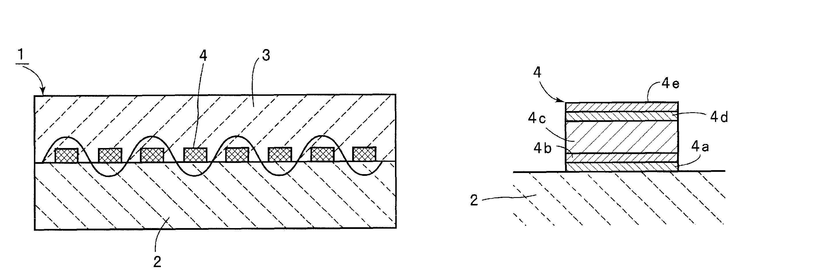
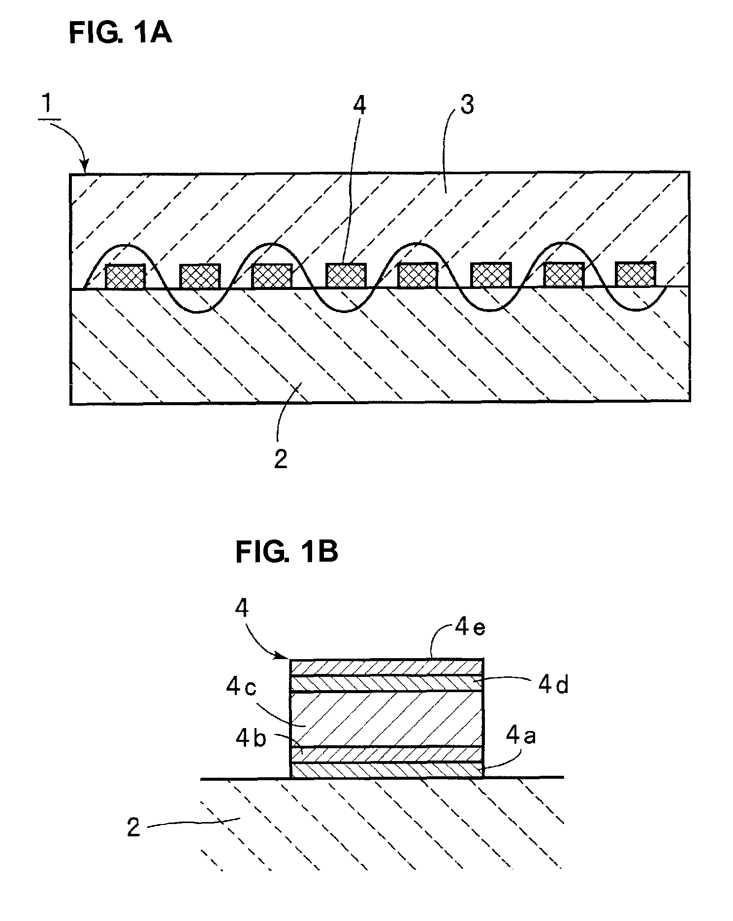
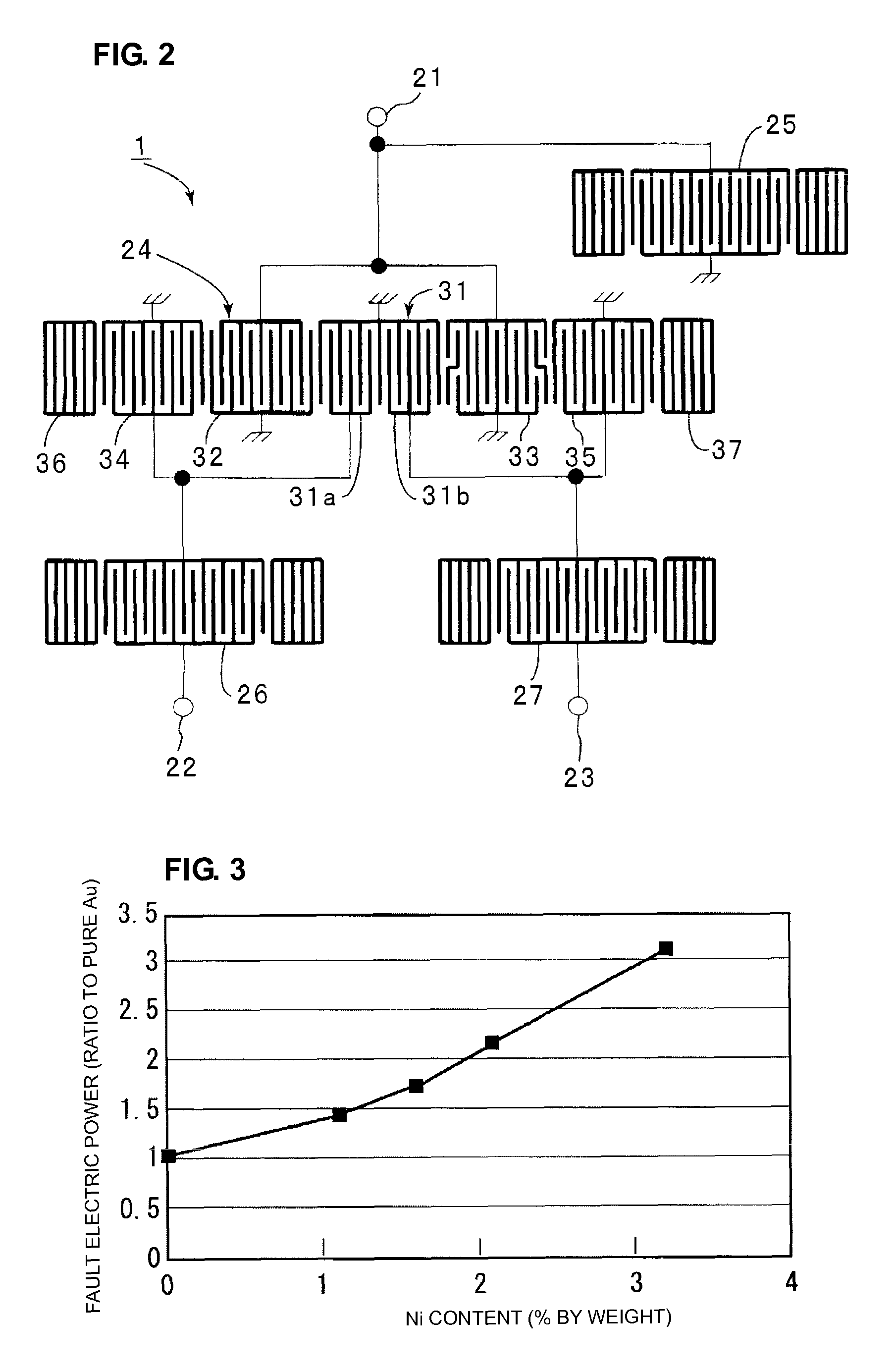
FIG. 1A is a schematic front sectional view, FIG. 1B is a schematic enlarged front sectional view showing an electrode structure, and FIG. 2 is a plan view showing the electrode structure, for illustrating a boundary acoustic wave filter device according to a preferred embodiment of the present invention.

A boundary acoustic wave filter device 1 of this preferred embodiment includes a piezoelectric substance 2 and a dielectric substance 3 laminated on the piezoelectric substance 2. As the piezoelectric substance 2, a 15° Y-cut X-propagating LiNbO3 single crystal substrate is preferably used, for example. The dielectric substance 3 is preferably made of SiO2, for example. In addition, an electrode film 4 including an IDT is disposed at the boundary between the piezoelectric substance 2 and the dielectric substance 3, i.e., on the upper surface of the piezoelectric substance 2.

As the electrode film 4, an IDT and a longitudinally coupled resonator filter portion having a short-circuited...

example 2

Next, a one-port boundary acoustic wave resonator having an electrode structure shown in FIG. 4A was formed and evaluated. As shown in FIG. 4A, an electrode film 4 is deposited so as to include IDT 11 and reflectors 12 and 13 disposed on both sides of the IDT 11. Although not shown in FIG. 4A, a dielectric substance 3 is laminated to cover the electrode film 4 as in the preferred embodiment shown in FIG. 1A. In this experimental example, a 15° Y-cut X-propagation LiNbO3 single crystal substrate was used as the piezoelectric substance 2. After the electrode film 4 was formed by electron beam evaporation, SiO2 was deposited as the dielectric substance by RF magnetron sputtering.

As in the electrode film structure shown in FIG. 1B, in the electrode film 4, the IDT 11 was a laminated metal film of Ta film 4a / Pt film 4b / Au alloy film 4c / Pt film 4d / Ti film 4e. The Au alloy film 4c was deposited by electron beam evaporation using an Au alloy including about 1.1% by weight of Cu as an evapor...

example 3

For the boundary acoustic wave filter device 1 evaluated with respect to electric power resistance in Example 1, the Cu content in the Cu-including Au alloy film was changed within the range of about 0.01% to about 4.8% by weight to evaluate the relationship between the insertion loss and the Cu content. The results are shown in Table 2 and FIG. 7.

TABLE 2Cu content (% byweight)Insertion loss (dB)0.011.290.131.250.181.190.51.2111.241.11.281.21.231.71.292.11.333.81.494.81.59

Table 2 and FIG. 7 show that in an Au alloy film including Cu at a relatively low ratio, the insertion loss is relatively small and improved as compared to the Au alloy film 4c having a Cu content of 0, i.e., pure Au. In particular, at a Cu content within the range of about 0.01% to about 1.7% by weight, the insertion loss is less than that in the pure Au film not including Cu. Therefore, both the electric power resistance and the insertion loss can be improved by using an Au alloy film including Au and Cu at a rat...


PUM

PropertyMeasurementUnit
thicknessaaaaaaaaaa
thicknessaaaaaaaaaa
insertion lossaaaaaaaaaa

Abstract

A boundary acoustic wave device includes a piezoelectric substance, a dielectric substance laminated on the piezoelectric substance, and an electrode film disposed at a boundary between the piezoelectric substance and a dielectric substance, the device utilizing a boundary acoustic wave propagating along the boundary, wherein the electrode film is any one Au alloy electrode film of an Au alloy electrode film including Cu at a ratio of about 0.01% to about 4.8% by weight, an Au alloy electrode film including Pd at a ratio of about 0.01% to about 6.8% by weight, and an Au alloy electrode film including Ni at a ratio of about 0.01% to about 3.5% by weight.

Description

BACKGROUND OF THE INVENTION1. Field of the InventionThe present invention relates to a boundary acoustic wave device utilizing boundary acoustic waves propagating at a boundary between a piezoelectric substance and a dielectric substance and a method for manufacturing the same. More specifically, the present invention relates to a boundary acoustic wave device including an electrode film disposed between a piezoelectric substance and a dielectric substance, the electrode film being made of an Au alloy, and a method for manufacturing the same.2. Description of the Related ArtBoundary acoustic wave devices have been used as resonators and band-pass filters. A boundary acoustic wave device includes an IDT electrode that is disposed at a boundary between a first medium and a second medium. The boundary acoustic wave device uses boundary acoustic waves propagating along the boundary. Therefore, the boundary acoustic wave device can be mechanically supported on a surface opposite to the b...

Claims


Application Information

Patent Timeline
Patent Type & Authority Patents(United States)
IPC IPC(8): H01L41/083
CPCH03H9/0222H03H9/14541H03H9/131Y10T29/42
Inventor SAIJOU, SHINFUYUTSUME, TOSHIYUKI
Owner MURATA MFG CO LTD
Why Eureka
Try Eureka