Wavy composite structures

a composite material and composite material technology, applied in the direction of flexible pipes, resilient suspensions, solid-based dampers, etc., can solve the problems of affecting the accuracy of antenna aiming, the fatigue failure of structural components can occur at stresses well below static load limits, and the interruption of fibers is minimized. , the effect of reducing the interruption of fibers

Inactive Publication Date: 2011-03-15
PRATT WILLIAM F
View PDF3 Cites 16 Cited by
  • Summary
  • Abstract
  • Description
  • Claims
  • Application Information

AI Technical Summary

Benefits of technology

[0058]The ends of a CWCV structure according to the present invention may be restrained without significantly reducing the overall damping properties of the structure. There results a structural element possessing high axial stiffness and low weight. The structural elements of this invention offer markedly superior damping capabilities but are nevertheless useable with simple attachment fixtures and methods.
[0066]Wavy crossply structures that minimize the interruption of fibers thereby making the laminate stronger and less prone to failure.
[0067]Wavy composite pre-preg can be used to create virtually seamless crossply-like laminates with little or no interruption of fibers. This is simply accomplished by combining two or more wavy composite plies using opposing waveforms in its simplest form, or by using combinations of opposing and offset wavy composite waveforms to form the laminate. Such a laminate displays the properties of both unidirectional and crossply characteristics in that it can efficiently resist both axial and transverse shearing loads.
[0068]The fact that such a structure, which has fibers oriented in multiple directions, can be laid down with standard automation equipment (with as little as one axis of control) makes the structure and method economical. This is in contrast to laminates and methods used to make conventional unidirectional pre-preg based crossply laminates which cannot readily be automated. Additionally, experience has shown that wavy pre-preg can be more easily draped over contoured surfaces and tooling, further easing fabrication.
[0069]Finally, there is a finite maximum width to pre-preg (typically 60 inches maximum) which often causes laminators to have to splice and overlap sheets of unidirectional pre-preg together to form large laminae. This is especially true for off-axis unidirectional laminae. This introduces seams which often represent a significant weakness in the laminate (see FIG. 17, items 12-14). Wavy composite can be easily spliced together across the width without the need to interrupt the edge fibers (see FIG. 17, item 1 and 15). Since the present invention discloses how wavy composite laminae can be combined to produce crossply laminate structures, it is now possible to create such structures with a minimum of interruption of fiber continuity and without overlapping seams. In fact, wavy crossply tubes have been made that exhibit no discernable seam, have no interruption of fibers (except naturally at the ends of the tubes), and which display classic crossply laminate characteristics.

Problems solved by technology

For example, spacecraft vibrations initiated by attitude adjusting thrusters, motors and thermally induced stresses inhibit accurate aiming of antennas and other equipment carried by the craft.
Such vibrations can cause severe damage to the craft and its associated equipment.
Fatigue failure of structural components can occur at stresses well below static load limits.
While composite constructions have offered many significant advantages, such as excellent strength and stiffness properties, together with lightness and chemical resistance, the poor vibration damping properties of such construction have been of concern.
Damping occurs in these structures when a load causes differential movement of the opposing laminates, causing shearing in the sandwiched viscoelastic material.
Barrett's research showed that maximum shearing was experienced at the ends of the tubes and that clamping the constraining layers of the tube at the ends eliminated much of the damping effect, rendering the design impractical for most applications.
Some small percentage of total fibers in the tube may be oriented perpendicular to these fibers for hoop strength, to prevent separation, or to prevent buckling, but such fibers would not resist longitudinal loads.
To avoid cutting the fibers (except at the ends of a tube) the unidirectional pre-preg would have to be spirally wound on the tube which is a concept that sounds simple, but in reality is extremely difficult to do correctly.
This represents a potentially significant weakness in the crossply laminate.
Additionally, Pratt proposed the use of “wavy pre-preg for use with or without a separate viscoelastic layer” but did not teach or further amplify the construction or benefits.
Such methods are impractical in the extreme requiring an estimated 70 separate pieces of composite for one “damping device” that must be hand assembled for one shaft.
Such a shaft, if it can be accurately assembled at all, would weigh at least 50% more than a steel golf shaft and would therefore be unacceptable to the public.
In short, such a design is impractical if not impossible.
Since Olcott did not use methods of testing that produce an accurate characterization or material nomograph of the “V”, herringbone, or “zig-zag” laminate design, such an understanding of the material's true properties was never accomplished and Olcott and others were left to erroneously conclude that damping performance was a function of the length of the damping regions and not a function of the period and maximum angle of the pattern.
This means that these layers would be essentially non-functional and would contribute little if anything to the damping performance of the shaft.

Method used


Image

  • Wavy composite structures
  • Wavy composite structures
  • Wavy composite structures

Examples


Embodiment Construction

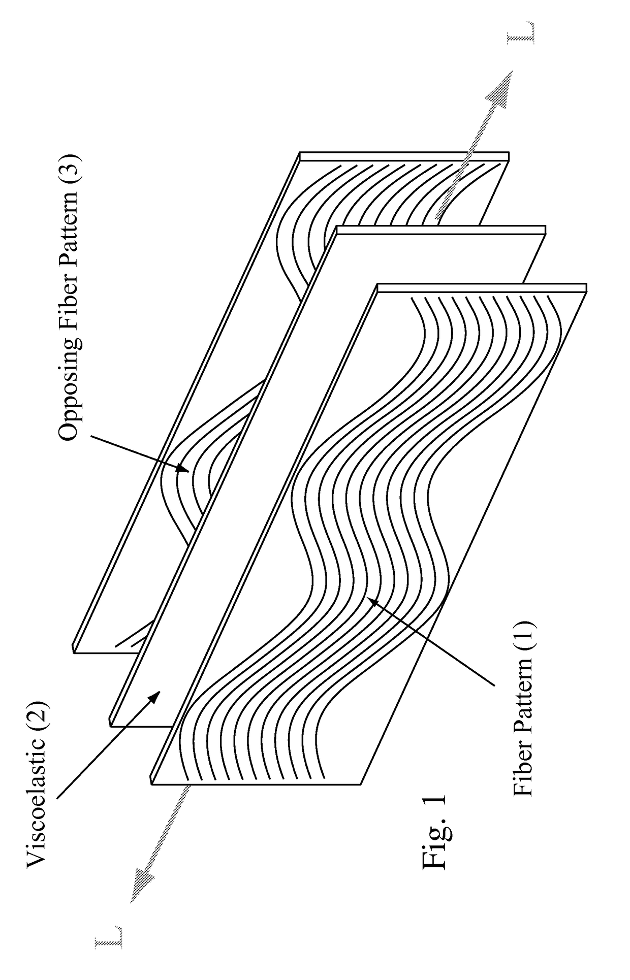
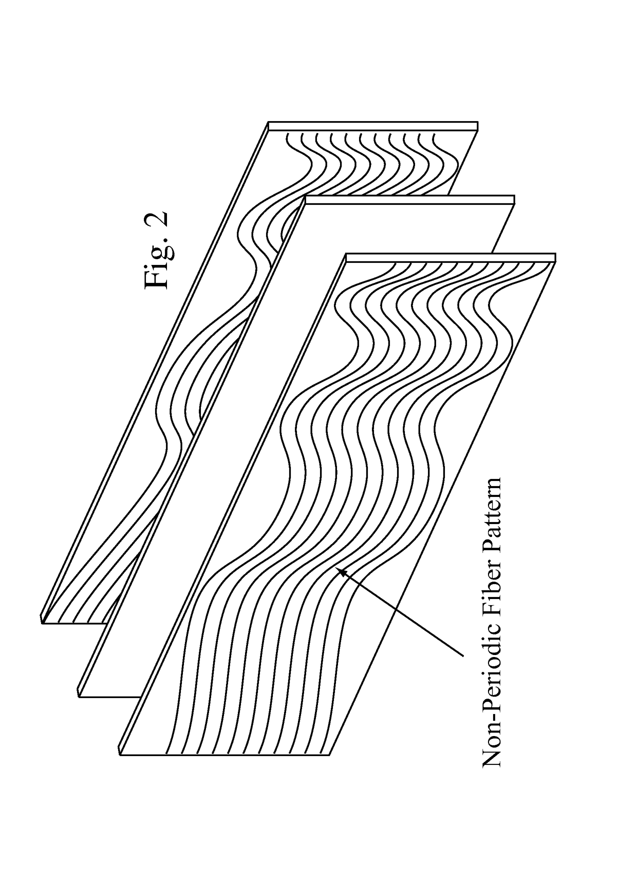
[0097]The most basic wavy composite structure is shown in FIG. 1 where a wavy composite layer (1) is combined with a viscoelastic layer (2) and an opposing wavy composite layer (3) with generally the same waveform as the first layer (1) but with a waveform that is offset by half a wavelength. The waveform need not be sinusoidal but may be any waveform that accomplishes the desired stiffness and damping performance. For example the waveform may vary along the length as shown in FIG. 2. In general, the waveform shown in FIG. 1 (1) and FIG. 2 would be described as sinuous. The wavy composite layers (1&3) may be made with bi-directional cloth as well as unidirectional fibers.

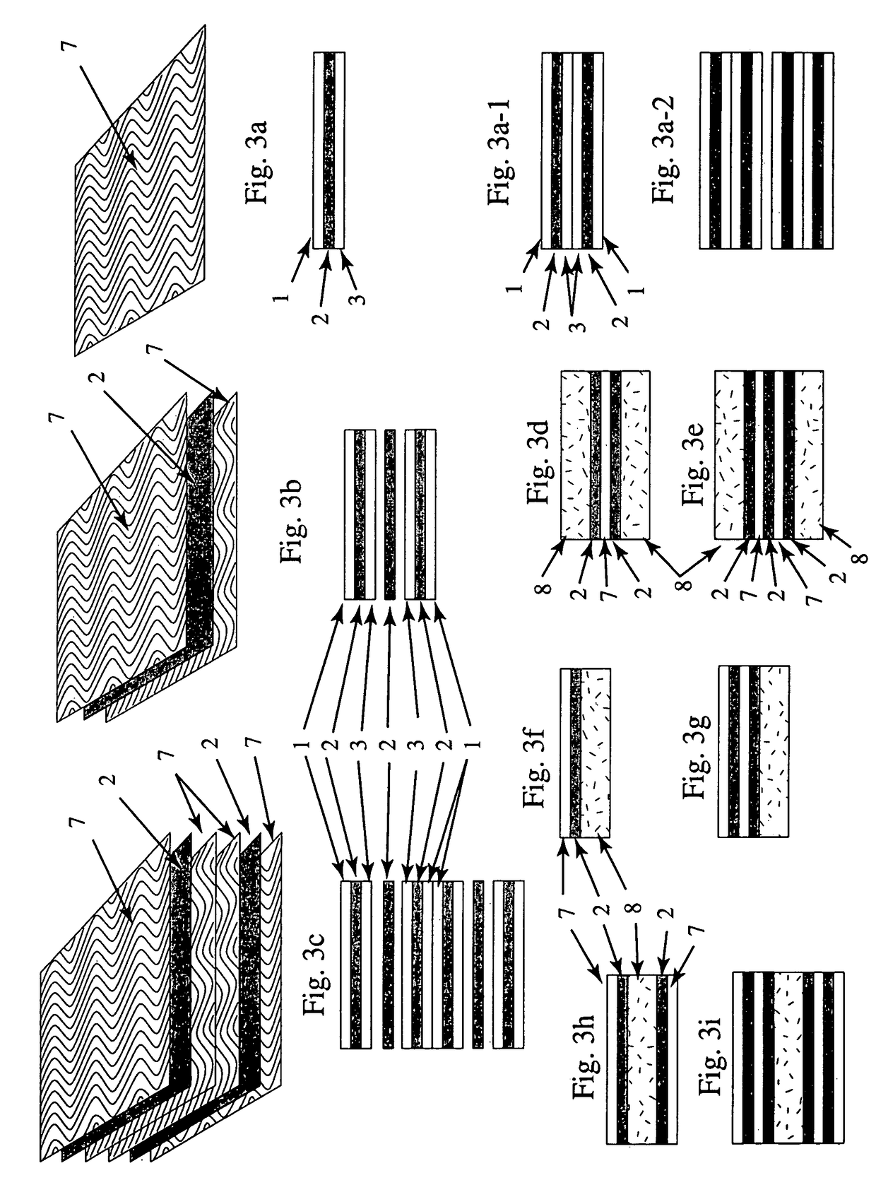
[0098]The CWCV shown in FIGS. 3-12 show a fiber pattern that is generally sinusoidal with a constant waveform, period, etc. Since the damping properties are frequency and temperature dependent, and since the selection of an optimal wave shape can be influenced by the desired structural response, a non-periodic, non-...


PUM

PropertyMeasurementUnit
angleaaaaaaaaaa
widthaaaaaaaaaa
angleaaaaaaaaaa

Abstract

Construction and advantages of improved wavy composite structures made from wavy composite, unidirectional composites, and damping materials is revealed. By combining wavy composite laminae in various waveforms, offsets, angular orientations and material combinations, it is possible to provide axial, torsion, or shear properties equivalent to unidirectional materials but without the limitations related to fiber discontinuity, labor costs for fabrication, and weakness at seams where laminates overlap. By combining wavy composite layers with unidirectional crossplies, or by using woven mats with various fill fiber levels where the warp fibers are sinuously arranged, improved strength and damping is possible. Several examples of both wavy crossply laminates and unidirectional crossply laminates are analyzed and compared.

Description

[0001]This application is a continuation-in-part of application Ser. No. 09 / 952,089, filed Sep. 10, 2001, now abandoned which is a continuation-in-part of application Ser. No. 09 / 238,873, filed Jan. 27, 1999, now U.S. Pat. No. 6,287,664, which claims the benefit of provisional Application No. 60 / 072,975, filed Jan. 29, 1998, and which is a continuation-in-part of application Ser. No. 08 / 970,141, filed Nov. 14, 1997, now U.S. Pat. No. 6,048,426; application Ser. No. 09 / 952,089 also claims the benefit of provisional Application No. 60 / 240,645, filed Oct. 16, 2000, provisional Application No. 60 / 251,094, filed on Dec. 1, 2000.TECHNICAL FIELD[0002]The present invention relates to fiber reinforced resin matrix composites, and more particularly, to improved crossply laminate structures made from wavy composite materials. Such materials and structures made from wavy composites have enhanced structural properties including improved damping, stiffness, strength, and represent a greatly enhan...

Claims


Application Information

Patent Timeline
Patent Type & Authority Patents(United States)
IPC IPC(8): F16F1/14B32B1/08B32B5/02A63B49/10A63B53/10A63B59/06A63C5/12B29C70/08B29C70/20B32B5/26B63B15/00F16C3/02F16F1/366F16F9/30
CPCA63C5/12A63C5/126B29C70/086B29C70/202B32B5/26F16C3/026F16F1/366F16F9/30A63B49/10Y10S180/902A63B59/0092A63B59/06A63B2209/02B29K2995/0091B29L2031/52B29L2031/75B63B15/0083Y10T428/24083Y10T428/139Y10T428/1393Y10T464/50A63B53/10A63B60/54A63B2102/18A63B59/50F16C2326/06F16F15/10A63B60/00
Inventor PRATT, WILLIAM F.
Owner PRATT WILLIAM F
Why Eureka
Try Eureka