Pulp mould and use of pulp mould

a pulp mould and mould body technology, applied in the field of pulp moulds, can solve the problems of distortion and deformation deficiencies, complicated shape of conventional pulp moulded objects, distortion of packaging materials, etc., and achieve the effect of minimizing or eliminating some disadvantages

Inactive Publication Date: 2011-03-22
PAKIT INT TRADING CO INC
View PDF48 Cites 15 Cited by
  • Summary
  • Abstract
  • Description
  • Claims
  • Application Information

AI Technical Summary

Benefits of technology

[0011]It is an object of the invention to provide a pulp mould that eliminates or at least minimizes some of the disadvantages mentioned above. This is achieved by presenting a pulp mould for moulding of objects from fibre pulp, comprising a sintered moulding surface and a permeable base structure where the moulding surface comprises at least one layer of sintered particles with an average diameter within the range 0.01-0.19 mm, preferably in the range 0.05-0.18 mm. This provides the advantage that the outermost layer of the moulding surface has fine structure with small pores in order to produce a pulp moulded object with a smooth surface and to contain fibres between a female and male mould preventing them from entering the same moulds and at the same time allowing fluid or vaporised fluid to emanate.

Problems solved by technology

The shape of these products is often complicated and in many cases they have a short expected time presence in the market.
Conventional pulp moulded objects have often been limited to packaging materials since they have had a competitive disadvantage in relation to products for example made of plastic.
This however creates distortions and deformations deficiencies in the resulting product.
Furthermore the drying process consumes high amounts of energy.
This is however complicated, time consuming and costly.
Furthermore the grid from the wire mesh as well as the welding spots is often apparent in the surface structure of the resulting product giving an undesirable roughness in the final product.
Furthermore the method of applying the wire mesh sets restrictions of the complexity of shapes for the moulding die making it impossible to form certain configurations in the shape.
This process is however complicated.
All prior art methods related to the production of a pulp mould, including the above disclosed methods, present some disadvantage.

Method used


Image

  • Pulp mould and use of pulp mould
  • Pulp mould and use of pulp mould
  • Pulp mould and use of pulp mould

Examples


second embodiment

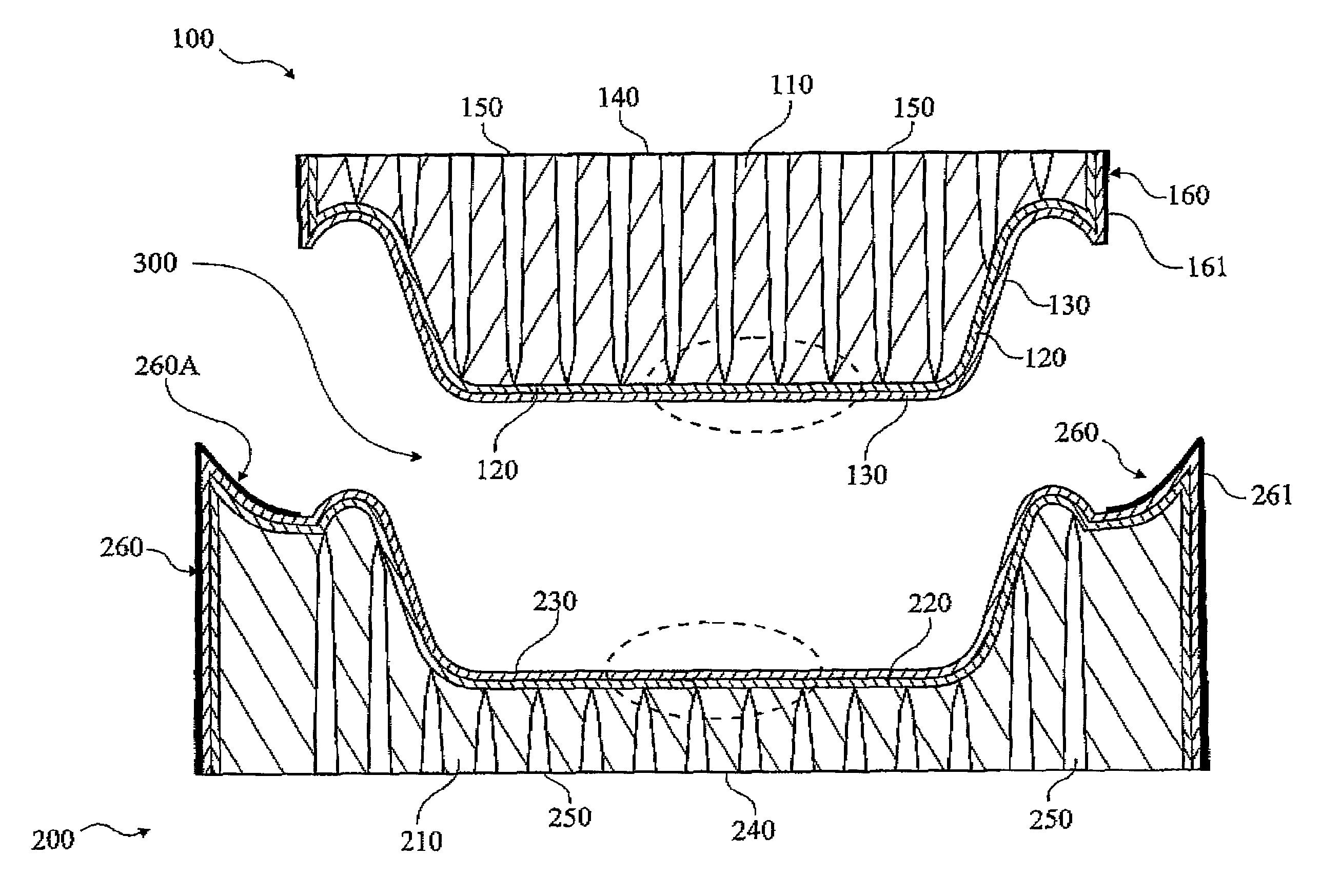
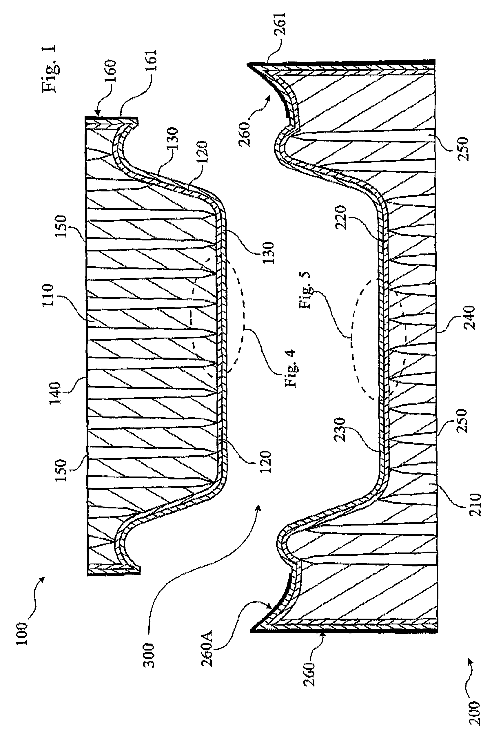
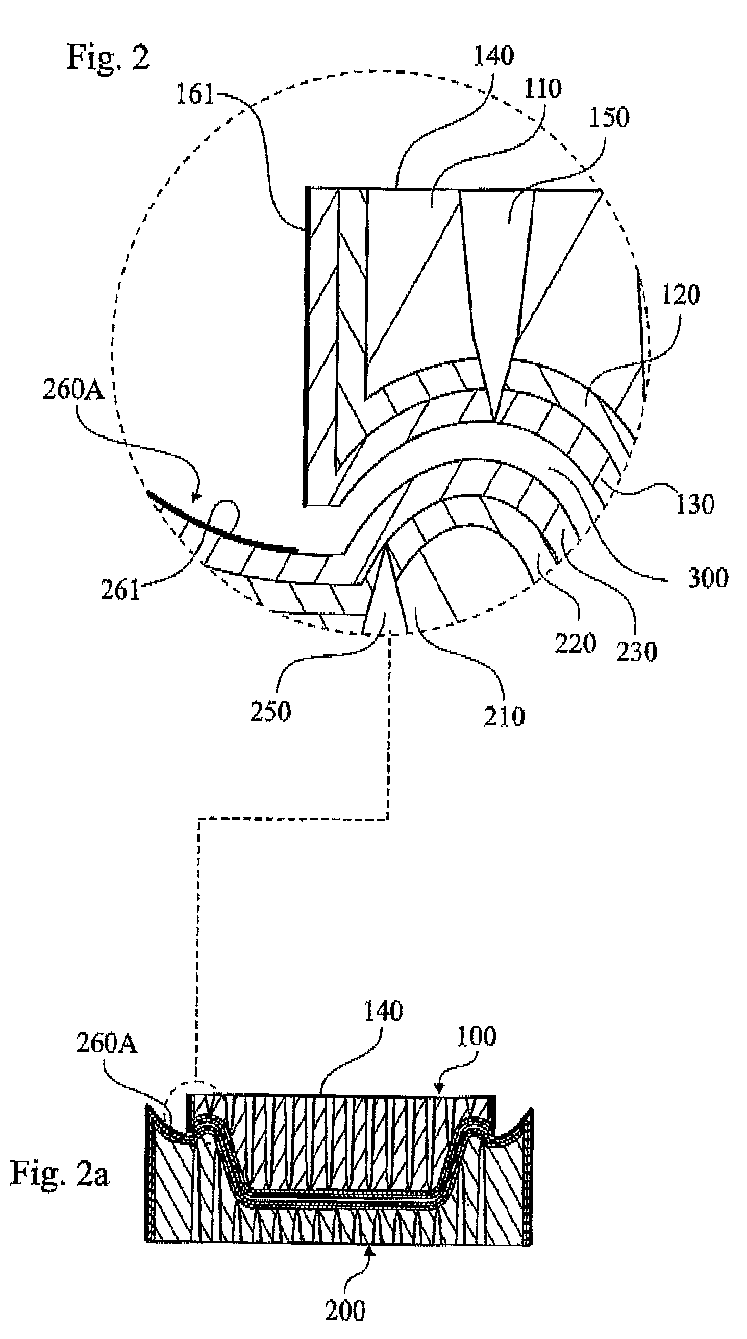
[0057]In FIGS. 2′, 2a′ according to the invention there is shown the position of the two mould halves 100, 200 during the heat press forming action. As can be seen there is formed a forming space 300 between the mould surfaces 130, 230, that is about 1 mm., preferably in the range 0.5-2 mm. As also can be seen from FIG. 2′ the mating surfaces 161, 261 of the mould halves 100, 200, do form a substantially smaller gap 300′ than the forming space 300. The mating surfaces 161, 261 is somewhat tilted to the left as is shown by the angle α in order to facilitate introduction of the male 100 into the female mould 200. Also it can be seen that the bottom surface 140 of the male mould is above the level of the upper portion 260A of the female mould, i.e. there is formed a gap between the support and heat plate 410 (see FIG. 10) of the male mould 100 and the female mould 200, which is feasible thanks to the arrangement according to the inventive process where the applied pressure may be direc...

first embodiment

[0062]The base structure 110, 210 of the shown embodiment contains sintered metal powder 111, 211 of the fabricate Callo 200 from the above mentioned Callo AB. Callo 200 is a spherical metal powder with a particle size range between 0.71-1.00 mm and a theoretical pore size of about 200 μm and a filter threshold of about 100 μm. The chemical composition of Callo 200 is 89% Cu and 11% Sn. As a way of example a sintered structure using Callo 200 and sintered to a density of 5.5 g / cm3 and a porosity of 40 vol-%, would have about the following characteristics; tensile strength 3-4 kp / mm2, elongation 4%, coefficient of heat expansion 18·10−6, specific heat at 293 K is 335 J / (kg·K), maximum operative temperature in neutral atmosphere 400° C. The pores 112, 212 of the base structure 110, 210 in the first embodiment has thus a theoretical pore size 112d, 212d of 200 μm, enabling liquid and vapour to be evacuated through the pore structure.

[0063]FIG. 8 shows a part of the moulding surface 130...


PUM

PropertyMeasurementUnit
diametersaaaaaaaaaa
diametersaaaaaaaaaa
diametersaaaaaaaaaa

Abstract

This invention relates to a porous pulp mold comprising sintered particles and a plurality of drainage channels. The pulp mold of the invention can be produced in a fast and cost effective way. The molding surface of the invention comprises small pore openings, to evacuate fluid and prevent fibers from entering the pulp mold. Furthermore the pulp mold of the invention comprises drainage channels improving the drainage capabilities of the pulp mold. The molding surface can be heated to at least 200° C., due to high heat conductivity of the pulp mold and its ability to withstand high temperatures.

Description

[0001]This application is a 371 of PCT / SE05 / 01771 filed on 25 Nov. 2005TECHNICAL FIELD[0002]The present invention relates to a pulp mould for moulding three-dimensional pulp objects that can be used in a wide variety of applications. More specifically the objects are formed by using fibre slurry comprising a mixture of mainly fibres and liquid. The fibre slurry is arranged in the mould and part of the liquid is evacuated and a resulting fibrous object is produced.BACKGROUND OF THE INVENTION[0003]Packagings of moulded pulp are used in a wide variety of fields and provide an environmental friendly packaging solution that is biodegradable. Products from moulded pulp are often used as protective packagings for consumer goods like for instance cellular phones, computer equipment, DVD players as well as other electronic consumer goods and other products that need a packaging protection. Furthermore moulded pulp objects can be used in the food industry as hamburger shells, cups for liquid ...

Claims


Application Information

Patent Timeline
Patent Type & Authority Patents(United States)
IPC IPC(8): D21J1/06D21JD21J3/00D21J7/00
CPCD21J7/00D21J3/00
Inventor NILSSON, BJORNGRAFFTON, LARSBASKMAN, LEIF
Owner PAKIT INT TRADING CO INC
Why Eureka
Try Eureka