Backprojection reconstruction method for undersampled MR imaging

a backprojection reconstruction and imaging technology, applied in tomography, instruments, applications, etc., can solve the problems of much shorter scan time, and achieve the effect of improving the backprojection method and shortening the scan tim

Active Publication Date: 2011-03-29
WISCONSIN ALUMNI RES FOUND
View PDF13 Cites 10 Cited by
  • Summary
  • Abstract
  • Description
  • Claims
  • Application Information

AI Technical Summary

Benefits of technology

[0016]The present invention is a new method for reconstructing magnetic resonance images, and particularly, an improved backprojection method. A composite image is acquired as part of the MRI scan, and it is reconstructed to provide a priori knowledge of the subject being imaged. This composite image is used during the reconstruction of highly under sampled image frames to weight the distribution of backprojected views in each image frame. As a result, far fewer projection views need be acquired resulting in a much shorter scan time. A speed increase factor (R) from 10 to 100 is possible depending on the details of the image.
[0025]Another aspect of the present invention is the application of the highly constrained image reconstruction method to contrast enhanced magnetic resonance angiography (“CEMRA”). With CEMRA, images of subject vasculature are acquired both before and after administration of a contrast agent. The former image serves as a mask which is subtracted from the contrast enhanced image to remove all stationary tissues from the final angiogram. With the image reconstruction method of the present invention the mask can be subtracted in additional ways to enhance its effectiveness. First, the mask image can be subtracted from the composite image before it is used to reconstruct the final image. Or, each k-space projection in the acquired image data set may have the corresponding k-space projection in the mask data set subtracted from it prior to its highly constrained backprojection. Or, both of the above mask subtraction methods can be used during the same reconstruction.

Problems solved by technology

As a result, far fewer projection views need be acquired resulting in a much shorter scan time.

Method used


Image

  • Backprojection reconstruction method for undersampled MR imaging
  • Backprojection reconstruction method for undersampled MR imaging
  • Backprojection reconstruction method for undersampled MR imaging

Examples


Embodiment Construction

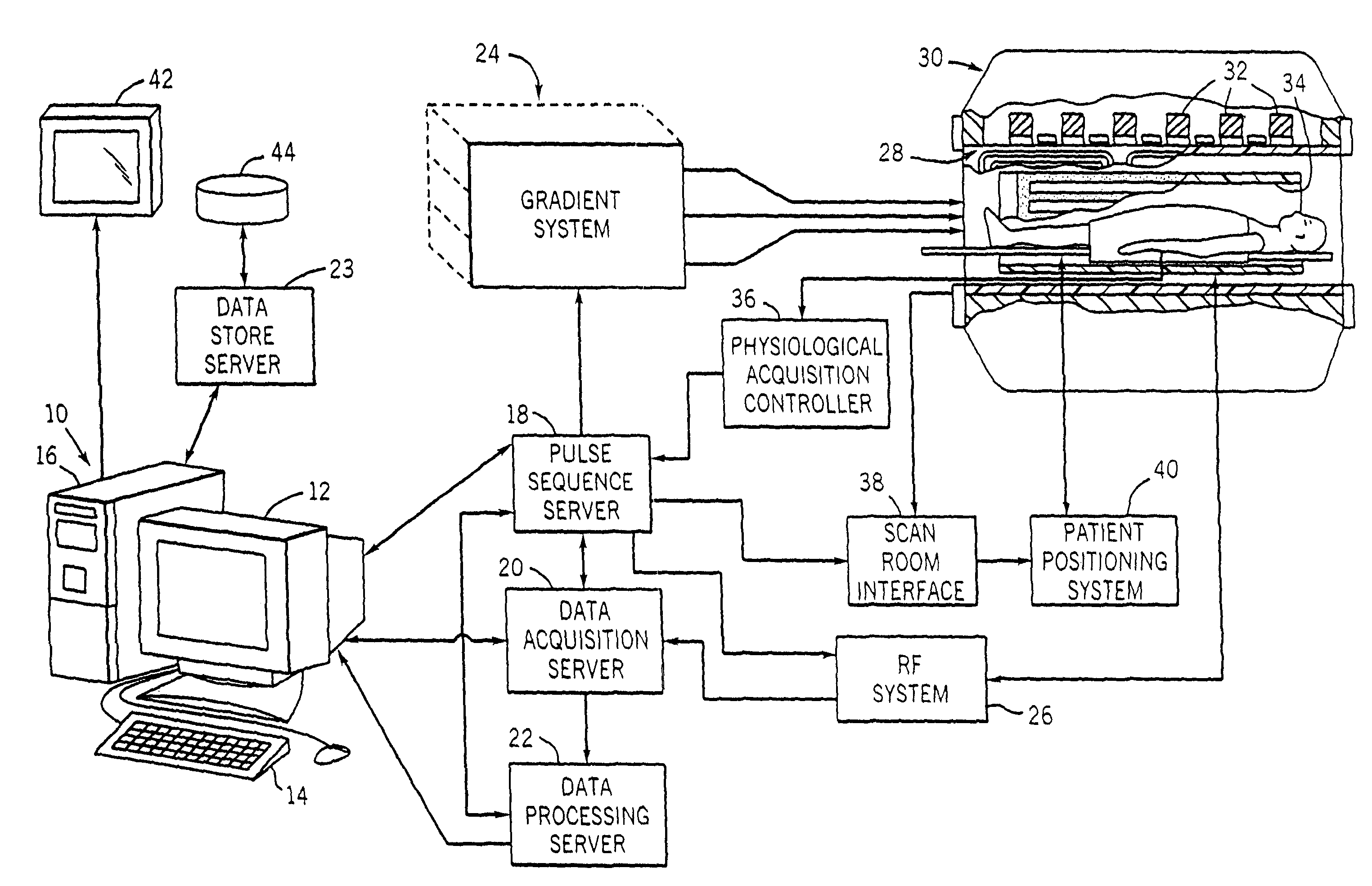
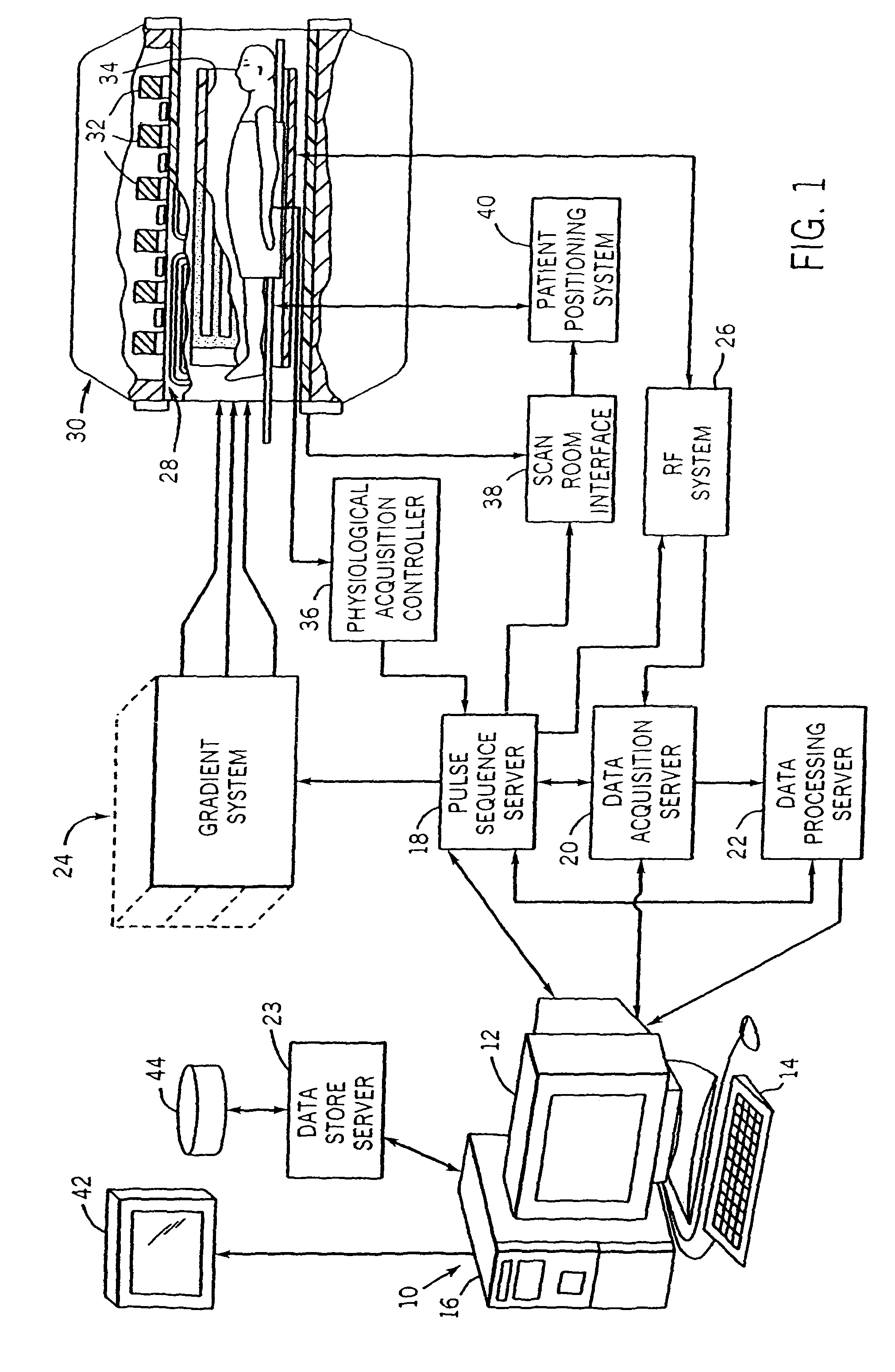
[0046]Referring particularly to FIG. 1, a preferred embodiment of the invention is employed in an MRI system. The MRI system includes a workstation 110 having a display 112 and a keyboard 114. The workstation 110 includes a processor 116 which is a commercially available programmable machine running a commercially available operating system. The workstation 110 provides the operator interface which enables scan prescriptions to be entered into the MRI system.

[0047]The workstation 110 is coupled to four servers: a pulse sequence server 118; a data acquisition server 120; a data processing server 122, and a data store server 23. In the preferred embodiment the data store server 123 is performed by the workstation processor 116 and associated disc drive interface circuitry. The remaining three servers 118, 120 and 122 are performed by separate processors mounted in a single enclosure and interconnected using a 64-bit backplane bus. The pulse sequence server 118 employs a commercially a...


PUM


Abstract

Two-dimensional or three-dimensional, time-resolved MR frame images are acquired during a dynamic study of a subject. A composite MR image is produced and this is used to reconstruct each image frame by weighting the backprojection of each projection view acquired for that image frame. The composite image may be reconstructed from views acquired separately, or it may be produced by combining views acquired during the course of the dynamic study. A number of different clinical applications of the method are described.

Description

CROSS-REFERENCE TO RELATED APPLICATIONS[0001]This application claims the benefit of U.S. Provisional patent application Ser. No. 60 / 697,607 filed on Jul. 8, 2005 and entitled “Backprojection Reconstruction Method For Undersampled Time-Resolved MR Imaging;” and U.S. Provisional patent application Ser. No. 60 / 719,445, filed on Sep. 22, 2005 and entitled “Highly Constrained Image Reconstruction Method”.STATEMENT REGARDING FEDERALLY SPONSORED RESEARCH[0002]This invention was made with government support under Grant No. 1R01HL72260-01 awarded by the National Institute of Health. The United States Government has certain rights in this invention.BACKGROUND OF THE INVENTION[0003]The field of the invention is magnetic resonance imaging (“MRI”), and particularly, the reconstruction of MR images.[0004]Magnetic resonance imaging uses the nuclear magnetic resonance (NMR) phenomenon to produce images. When a substance such as human tissue is subjected to a uniform magnetic field (polarizing field...

Claims


Application Information

Patent Timeline
Patent Type & Authority Patents(United States)
IPC IPC(8): A61B5/05G01V3/00
CPCA61B5/055A61B6/032A61B6/037A61B6/4441A61B6/507G01R33/561G06T11/006G01R33/4824A61B5/7257G01R33/5619G01R33/56308
Inventor MISTRETTA, CHARLES A.
Owner WISCONSIN ALUMNI RES FOUND
Why Eureka
Try Eureka