Method for maintaining the phase difference of a positioning mirror as a constant with respect to a high speed resonant mirror to generate high quality images

a technology of positioning mirror and resonant mirror, which is applied in the field of video display, can solve the problems of reducing the beam envelope, reducing the amplitude of the beam sweep, and complex problems, and achieve the effect of preventing variations in the vertical positioning of the first scan lin

Active Publication Date: 2011-04-05
TEXAS INSTR INC
View PDF7 Cites 6 Cited by
  • Summary
  • Abstract
  • Description
  • Claims
  • Application Information

AI Technical Summary

Benefits of technology

[0008]These and other problems are generally solved or circumvented, and technical advantages are generally achieved by the embodiments of the present invention, which provides a method of preventing variations in the vertical positioning of the first scan line of an image frame.
[0016]In one embodiment, the “arming” signal is based on sensors, which monitor the position of the low-speed mirror. Alternately, in another embodiment, the position is inferred or calculated based on the driving waveform, which will have a substantially constant phase lead relative to the actual position. This embodiment may allow the elimination of sensors resulting in lower system cost and complexity. However, due to the greater variations in the phase between the high speed mirror drive signal and the high speed mirror position, calculated values for the trigger signals may not be accurate, and therefore, a sensor will typically be required to generate the “trigger” signals.

Problems solved by technology

Unfortunately, the problem is more complex than that.
At the same time, however, the high frequency mirror must run or oscillate at substantially its resonant frequency, since driving a high-Q mirror at a frequency only slightly different than the resonant frequency will result in a significant decrease in the amplitude of the beam sweep (i.e. reduce the beam envelope).
This would cause a significant and unacceptable compression of the image on the display.

Method used


Image

  • Method for maintaining the phase difference of a positioning mirror as a constant with respect to a high speed resonant mirror to generate high quality images
  • Method for maintaining the phase difference of a positioning mirror as a constant with respect to a high speed resonant mirror to generate high quality images
  • Method for maintaining the phase difference of a positioning mirror as a constant with respect to a high speed resonant mirror to generate high quality images

Examples


first embodiment

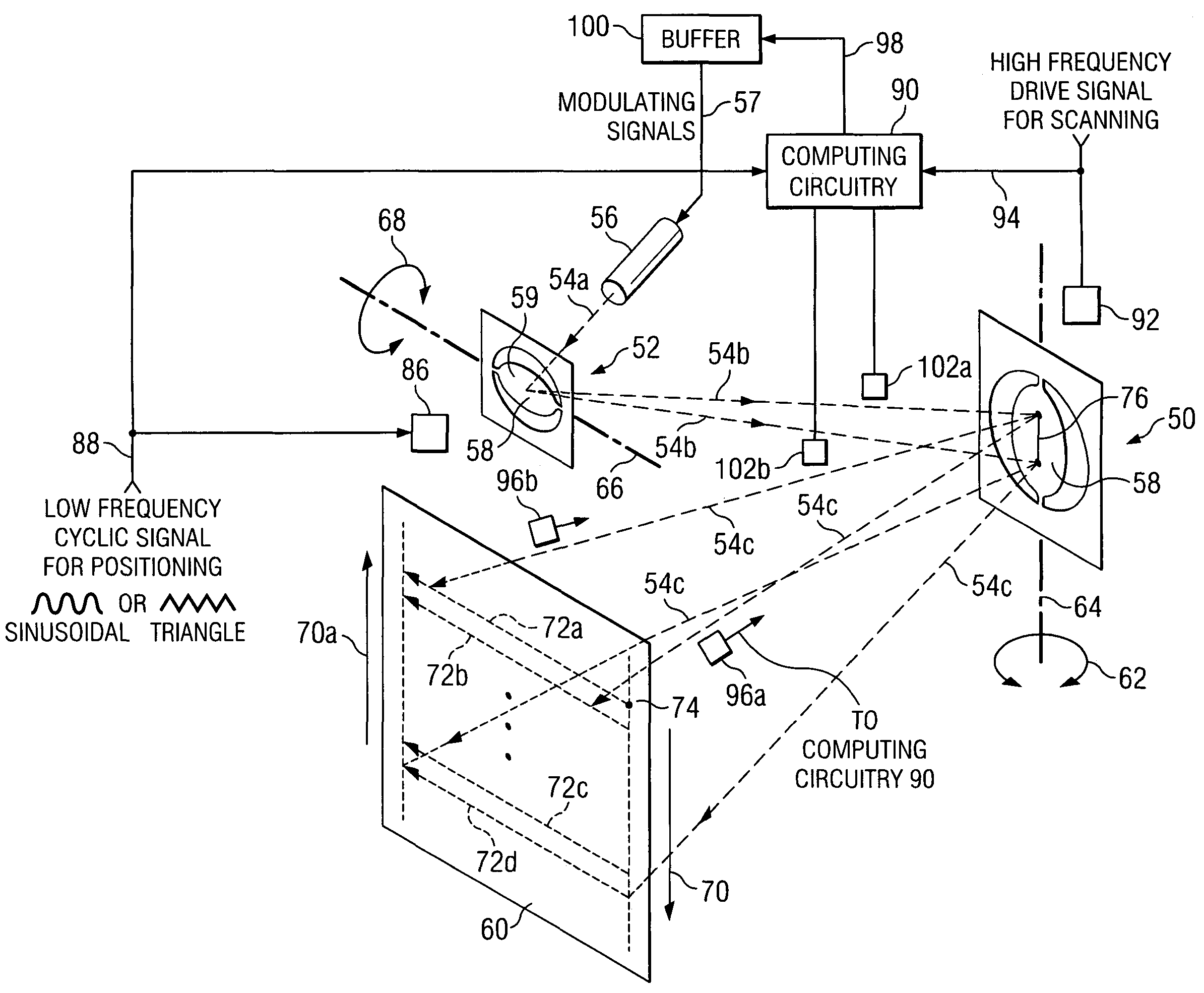
[0044]Therefore, according to the invention, since the speed of both mirrors is known, and since the movement or position of both mirrors can be precisely determined at a specific time, the phase difference can be maintained as a constant by adding or removing a calculated number of the storage locations in the same manner as discussed above with respect to FIGS. 3A and 3B. However, the number of storage locations or discrete values added or subtracted to fine adjust and maintain the phase difference as a constant will typically be significantly less than the number discussed above for synchronizing the incoming data stream with the low frequency positioning mirror.

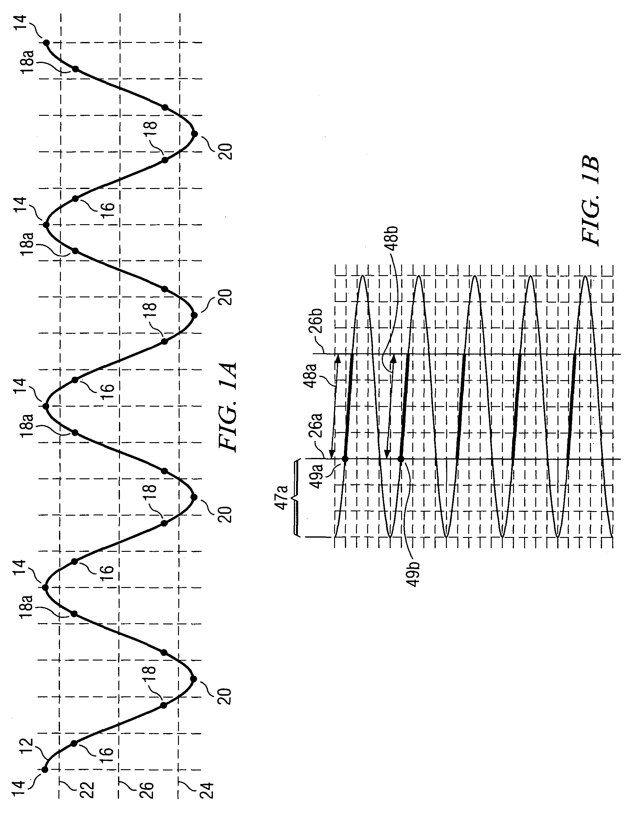
[0045]It is also important to note that adjusting (expanding or compressing) the peak portions of the cyclic slow speed drive signal is shown as being accomplished in the upper peak portions of the drive signal (the portion above line 22), while the video signal is blanked or cut off. It should also be appreciated that al...

second embodiment

[0047]Therefore, a second embodiment for maintaining or adjusting the phase difference between the arming signal and the trigger signal is to slightly modify the sample time Ts or clock rate at which a selected number of the cycle drive discrete samples are delivered. As an example only, Ts may be modified from 10 microseconds (μ) to 10.3 microseconds (μ) for a selected number of discrete values in the peak portion of the cycle and the nominal Ts would then be restored before the display portion of the cycle. This approach provides significantly improved resolution for maintaining the selected phase difference.

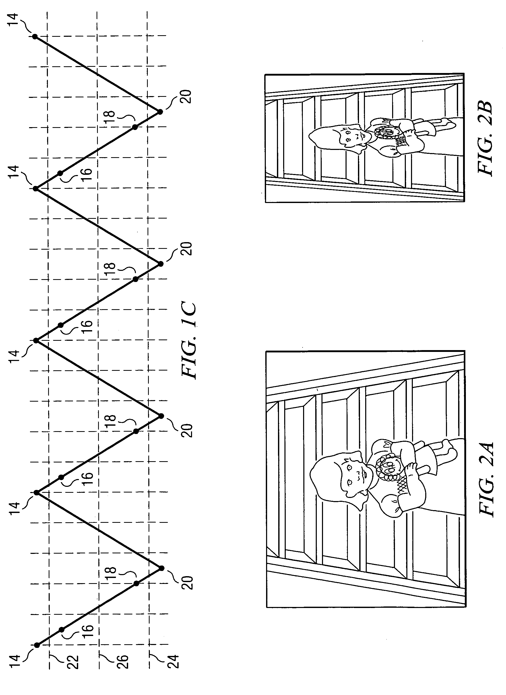
[0048]It should also be appreciated that although the above detailed discussion has been with respect to a “sinusoidal” slow speed drive signal, such as shown in FIG. 1A, the discussion is equally applicable to the repetitive “triangular shaped” drive signal such as illustrated in FIG. 1C. In addition, in the embodiments shown, the appropriate adjustment could also occur durin...


PUM


Abstract

System and method for synchronizing the low speed mirror movement of a mirror display system with incoming frame or video signals, and synchronizing buffered lines of video data to the independently oscillating scanning mirror. According to one embodiment of the invention, the peak portions of the low speed cyclic drive signal are synchronized with the incoming frames of video by compressing or expanding the peak portion or turn around portion so that each video frame begins at the same location on the display screen. The actual position of the high frequency mirror is determined by sensors and a “trigger” signal is generated to distribute the signals for each scan line such that the scan lines are properly positioned on the display.

Description

TECHNICAL FIELD[0001]The present invention relates to a video display comprising a high speed scanning mirror and a decoupled slow speed positioning mirror that moves orthogonally to the high speed mirror for generating scan or image lines to produce an image. The invention further relates to synchronizing the orthogonally moving low frequency mirror with the incoming video signals. More particularly, the invention relates to adjusting and maintaining the phase difference between the low frequency mirror and the sweep of the high speed scanning mirror that displays the first image line as a selected constant.BACKGROUND[0002]In recent years torsional hinged high frequency mirrors (and especially resonant high frequency mirrors) have made significant inroads as a replacement for spinning polygon mirrors as the drive engine for laser printers. These torsional hinged high speed resonant mirrors are less expensive and require less energy or drive power than the earlier polygon mirrors.[0...

Claims


Application Information

Patent Timeline
Patent Type & Authority Patents(United States)
IPC IPC(8): H04N5/66H04N3/14
CPCH04N9/3129G02B26/101G02B26/0833
Inventor OETTINGER, ERIC GREGORYNOXON, JAMES EUGENE
Owner TEXAS INSTR INC
Why Eureka
Try Eureka