Timing adjustment method for wireless communication apparatus

a wireless communication and timing adjustment technology, applied in the field of wireless transmitter/receiver, can solve the problems of signal quality degradation, low quality, and variation in delay amount, and achieve the effects of improving spurious output characteristics, improving quality, and simple structur

Inactive Publication Date: 2011-04-26
HITACHI LTD
View PDF36 Cites 6 Cited by
  • Summary
  • Abstract
  • Description
  • Claims
  • Application Information

AI Technical Summary

Benefits of technology

Unlike the conventional methods which directly measure a delay difference between an r signal and a θ signal, this invention judges the timing of the transmission signal and the timing of the feedback signal in relation to each other (one is behind or ahead of the other), and therefore a measure to compare the two can have a simple structure.
Furthermore, this invention uses a VCO (Voltage Controlled Oscillator) as a clock signal generating unit, thereby making it possible to follow changes in delay amount in a continuous manner and give the transmission signal improved spurious output characteristics compared to the conventional methods.
As a result, an output signal of a transmitter / receiver that employs EER is improved in quality and the efficiency of its power amplifier is enhanced. The output signal quality is also improved in a transmitter / receiver that employs other systems than EER while keeping the area and power consumption of a control circuit small.

Problems solved by technology

While being capable of adjusting a delay smaller than one clock, the method shown in FIG. 8 has a problem of signal quality degradation since quantization error remains in the adjustment amount, due to its inconsecutiveness, and the group delay characteristics of the filter make the amount of delay vary from frequency to frequency.
Although Δdd could be inserted in an analog region with the use of a delay line, the resultant performance is poor because causing a delay of accurate amount is difficult and the analog element is greatly fluctuated in characteristic by external factors such as a temperature variation.
In addition, discontinuously changing the delay amount to be inserted causes, at an instant, a discontinuous change in waveform of the transmission signal and it can worsen the spurious output characteristics of the transmission signal.
The method shown in FIG. 9 suffers from quantization error remaining in the adjustment amount as does the method of FIG. 8.
Furthermore, the method of FIG. 9 is for timing the transmission signal and the feedback signal with each other, not for adjusting a delay difference between the two components of the transmission signal, and therefore is not capable of solving the problem of EER.

Method used


Image

  • Timing adjustment method for wireless communication apparatus
  • Timing adjustment method for wireless communication apparatus
  • Timing adjustment method for wireless communication apparatus

Examples


first embodiment

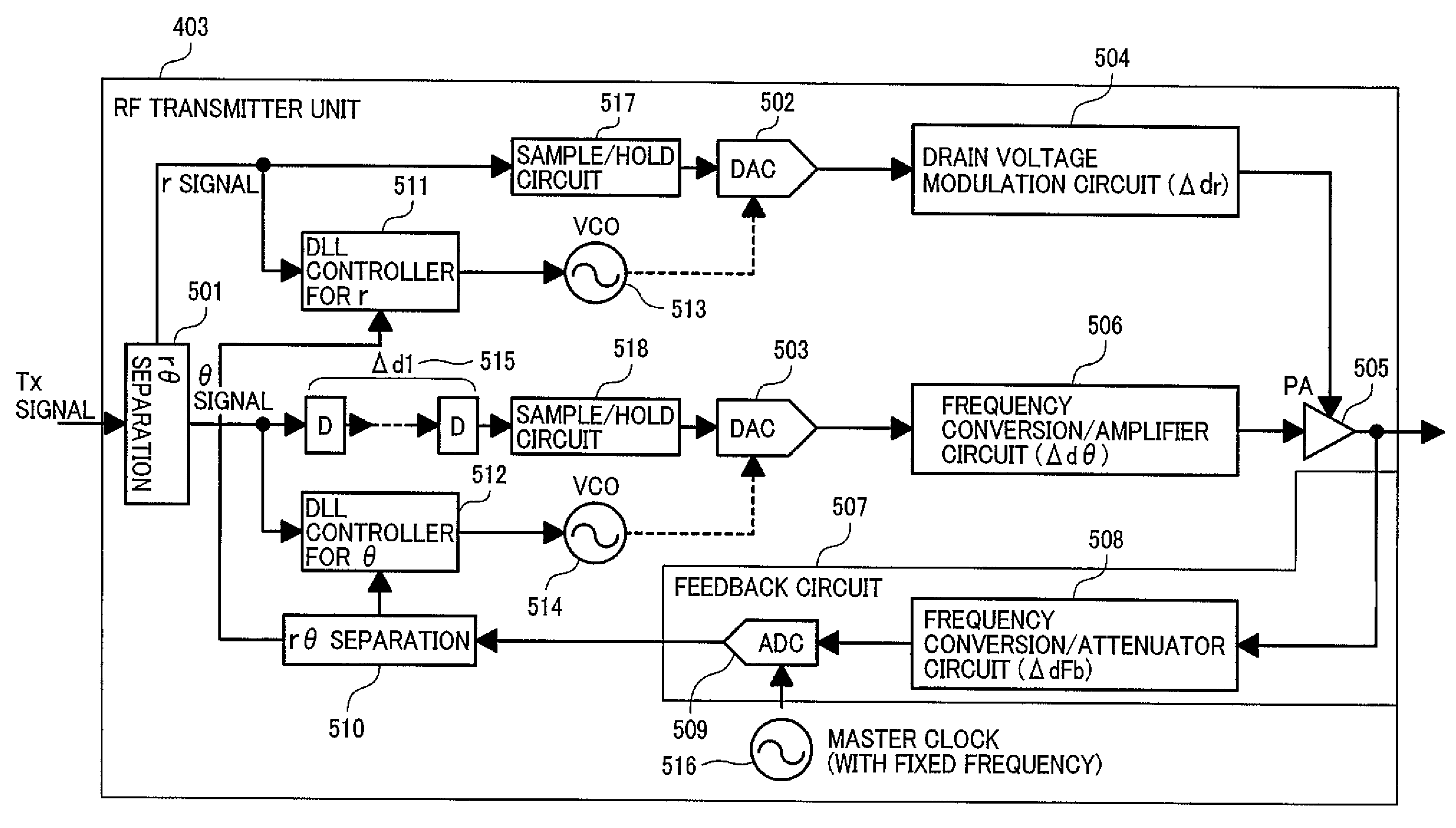
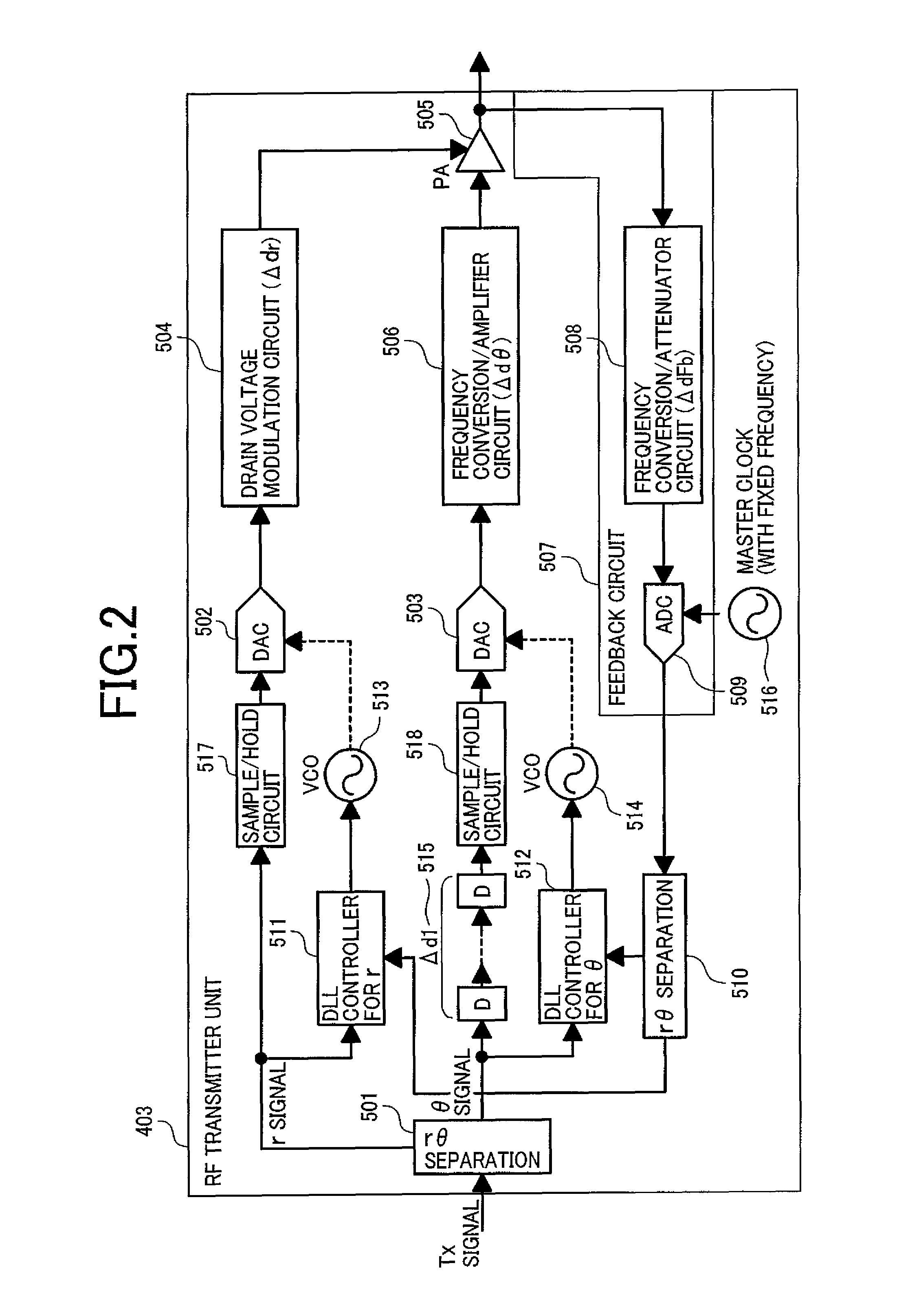
FIG. 2 is a block diagram showing the structure of the RF transmitter unit 403 according to this invention.

A transmission signal inputted from the baseband unit 402 is separated into an r (amplitude) component and a θ(phase) component by an rθ separation unit 501. The r component and the θ component are converted into analog signals in digital-to-analog converters (DAC) 502 and 503, respectively. The r signal is converted by a drain voltage modulation unit 504 into a signal to control the supply voltage (drain voltage) of a power amplifier (PA) 505. The converted signal is inputted to a supply terminal of the power amplifier 505, with the result that the envelope curve of an output signal of the power amplifier 505 resembles the waveform of the r signal. The θ signal receives, in a frequency-conversion and amplifier unit 506, frequency conversion to be converted to the RF bandwidth (up conversion) and power amplification. The amplified θ signal is inputted into a signal input termin...

second embodiment

FIG. 5 is a block diagram showing the structure of an RF transmitter unit 403 according to this invention.

In this embodiment, the timing of a feedback signal is adjusted with the timing of transmitting a θ signal as reference and the timing of transmitting an r signal is adjusted based on the thus adjusted timing of the feedback signal. This embodiment shares its basic structure with the first embodiment (FIG. 2) except a timing adjustment circuit of the RF transmitter unit 403. A detailed description on the structure common to this embodiment and the first embodiment will be omitted here.

In this embodiment, the master clock source 516 supplies clock signals to the θ signal DAC 503 whereas the VCO 513 and a VCO 801 supply clock signals to the r signal DAC 502 and the feedback signal ADC 509, respectively. The feedback signal is sampled and digitized by the ADC 509. Then the value of the feedback signal is held by a sample-and-hold circuit 802 to prevent the rθ separation unit 510, w...

third embodiment

FIG. 6 is a block diagram showing the structure of an RF transmitter unit 403 according to this invention.

This embodiment deals with one of adjustment methods to adjust, in a transmitter / receiver that employs other systems than EER and that modulates an I signal and a Q signal through paths of different delay amounts, the delay difference between the two signal paths, in order to show that this invention is applicable also when a wireless transmitter employs other systems than EER. This embodiment shares its structure, except the RF transmitter unit 403, with the first embodiment which is shown in FIG. 1. A detailed description on the structure common to this embodiment and the first embodiment will be omitted here.

An I signal and Q signal received from the baseband unit 402 are converted into analog signals by the DACs 901 and 902, respectively. The analog I and Q signals pass the filters 903 and 904, respectively, before combined with each other through modulation by a orthogonal ...


PUM


Abstract

A wireless communication device including: a transmitter including two DA converter units which convert two digital signals into analog signals; a combiner which combines the analog signals; a distributor which extracts a portion of the combined signal as a feedback signal; an AD converter which converts the feedback signal; an oscillator unit which supplies clock signals to operate the DA converter units and the AD converter; a first separation unit which separates the feedback signal converted by the AD converter into two signals; and a comparator unit which compares at least one of the two digital signals that are obtained by separating the inputted digital signal, or, at least one of the two digital signals that are separately inputted, with the feedback signal separated by the first separation unit, wherein the oscillator unit controls the output clock signals based on a result of the comparison by the comparator unit.

Description

BACKGROUNDThis invention relates to a wireless transmitter / receiver having a function of adjusting, by way of closed-loop feedback control, the timing of a transmission signal. In particular, the invention relates to a wireless transmitter / receiver that employs EER to adjust the timing of sending an r (amplitude) component and a θ (phase) component.For transmitters installed in base stations and terminals of cellular phone and other wireless communication systems, methods have been developed to separate a transmission signal into two components, process the two separately, and then recombine them as a transmission output. Known examples of such methods include one in which a transmission signal is separated into an I signal and a Q signal to be processed separately, and EER (Envelope Elimination and Restoration) in which a transmission signal is separated into an r (amplitude) component and a θ (phase) component to be processed separately.However, signals created by separating one s...

Claims


Application Information

Patent Timeline
Patent Type & Authority Patents(United States)
IPC IPC(8): H01Q11/12H04B1/04H03G3/30H04L7/02H04L27/00
CPCH03F1/3247H03F1/3282H03F3/189H03F3/24H04L7/0054H04B1/0475H04B1/0483H04B2001/0433H03F2200/451H03F1/34H04B1/04H04L7/02H04L27/00
Inventor SUZUKI, MAYHORI, KAZUYUKIYANO, TAKASHI
Owner HITACHI LTD
Why Eureka
Try Eureka