Tissue dissector apparatus

a tissue dissector and apparatus technology, applied in the field of surgical equipment, can solve the problems of increasing the difficulty of operation, difficult to retain the precise hand control needed to perform the surgical procedure, and difficulty in using different tools at the same time in the surgical cavity, and achieve the effect of enlarge the surgical cavity

Inactive Publication Date: 2011-05-10
MAQUET CARDIOVASCULAR LLC
View PDF603 Cites 43 Cited by
  • Summary
  • Abstract
  • Description
  • Claims
  • Application Information

AI Technical Summary

Benefits of technology

[0005]In accordance with the present invention, a tissue dissector is provided in which a cannula houses an endoscope, and a dilating element is coupled near the distal end of the cannula. The dilating element has an outer dimension which is greater than the diameter of the distal end of the cannula. This greater dimension serves to enlarge the surgical cavity as the cannula is advanced through the surgical site, thus allowing the cannula to track along the vessel while forming a working cavity and providing room within which additional surgical tools may operate safely. In one embodiment, the dilating element is in the shape of an oval, allowing compression of the surrounding tissue to occur atraumatically.
[0006]In an alternate embodiment, a locking mechanism is disposed on the cannula, and the dilating element is coupled to the locking mechanism when enlargement of the surgical cavity is required. In this embodiment, multiple dilating elements of differing outer dimensions may be employed responsive to the enlargement required. Various locking mechanisms may be employed in accordance with the current invention, including using screw threads disposed on the surface of the cannula, and mating internal screw threads in a bore hole through the dilating element to permit the dilating element to couple to the screw threads. Alternatively, the dilating element may include a bayonet-type fitting, with mating knobs on the associated surface portion of the cannula for locking the dilating element into place. Additionally, in one embodiment the tip and dilating element are a single detachable component, and may be coupled and decoupled to the main body of the cannula as desired. This greatly facilitates use of dilating elements of different dimensions.
[0007]The body of the cannula may be tapered from a smaller diameter near the distal end of the cannula to a larger diameter remote from the distal end of the cannula. The tip of the cannula is transparent to facilitate endoscopic viewing of the surgical cavity. The tapering of the distal end of the cannula may begin at a point forward of the distal end of the dilating element. This allows the tip of the cannula to track along the target vessel without the enlarged diameter of the dilating element preventing the tip from making contact with the target vessel. In one embodiment, the dilating element is made of rigid plastic to facilitate expansion of a working cavity and ease of translation through the surgical site. In another embodiment, the dilating element is made of a flexible material which compresses as the external walls exert force upon the cannula, but retains sufficient structural rigidity to accomplish the required enlargement of a working cavity. In yet another embodiment, the dilating element is made of flexible material and is shrouded within a retractable sheath which, in the extended position, encases the dilating element and thereby compresses the dilating element to a smaller diameter, and in a retracted position, allows the dilating element to expand and enlarge the working cavity.

Problems solved by technology

Using different tools simultaneously in a surgical cavity is difficult due to the small size of the surgical cavity.
Additionally, within the surgical cavity, the surrounding tissue typically collapses upon the cannula and surgical tools, increasing the difficulty of the operation, if performed without insufflation.
However, maintaining the surgical cavity open using insufflation with gas under pressure then also requires sliding gas-tight seals for each endoscopic instrument that is inserted into the surgical cavity.
However, use of a balloon to enlarge surgical cavities has the disadvantage that multiple balloon inflation and deflation tires the surgeon's hands, and makes it difficult to retain the precise hand control needed to perform the surgical procedure.
Also, manufacture of a balloon cannula requires manual mounting of the balloon in a tedious process that adds expense to the device.
Additionally, balloons have a potential for rupture during use and thereby disrupt the surgical procedure.

Method used


Image

  • Tissue dissector apparatus
  • Tissue dissector apparatus
  • Tissue dissector apparatus

Examples


Embodiment Construction

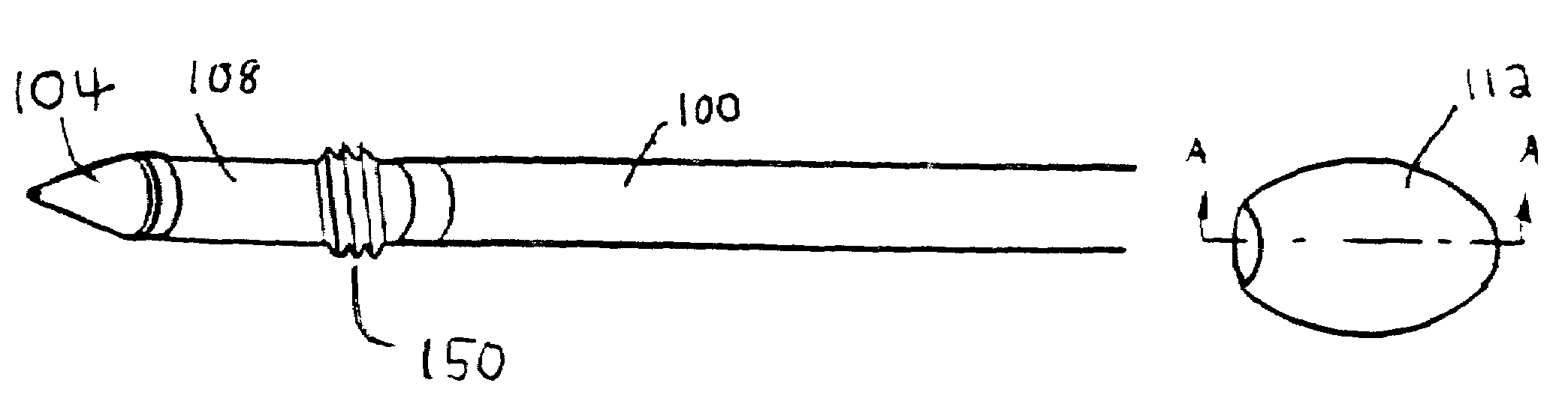
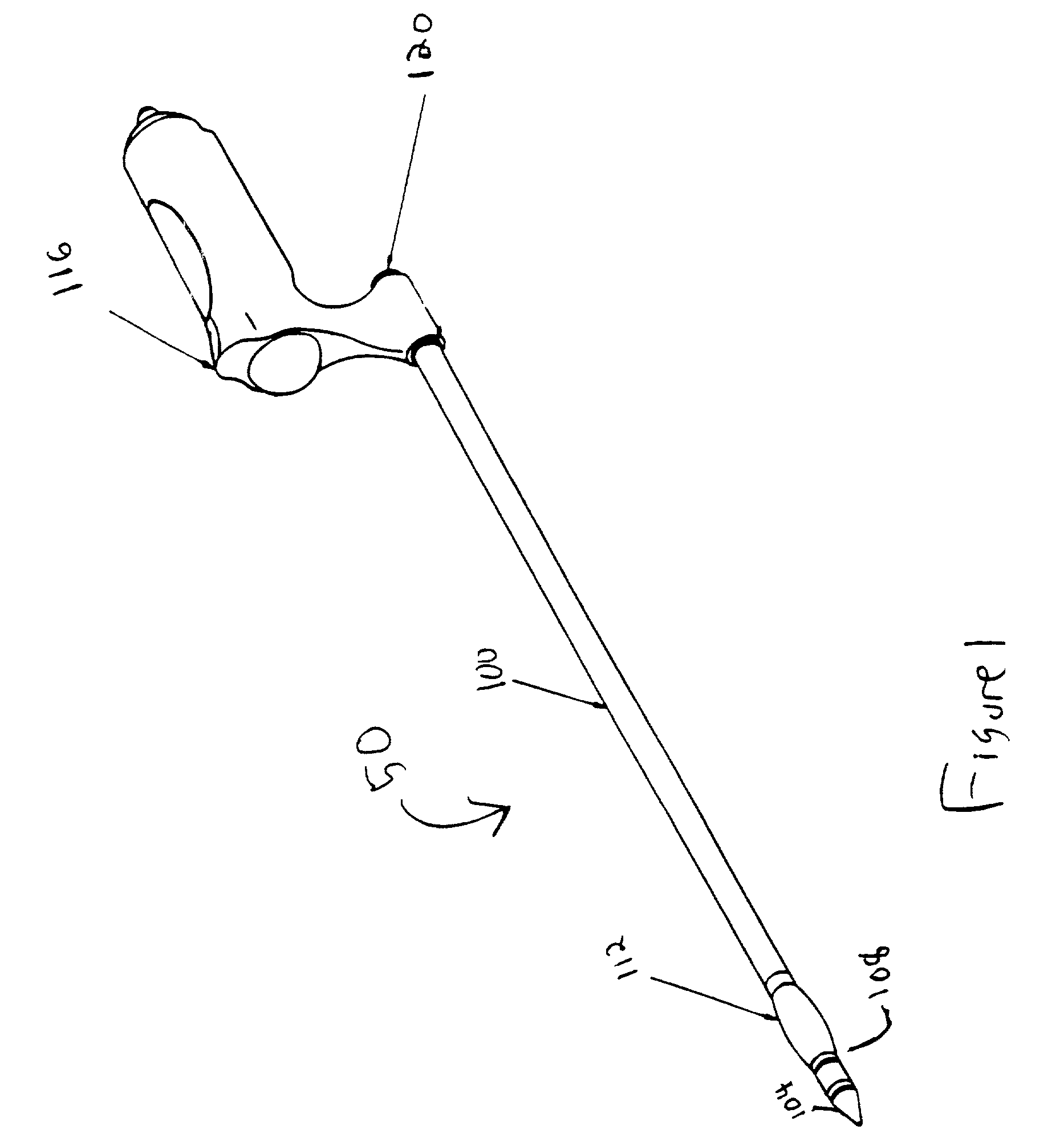
[0024]FIG. 1 illustrates a tissue dissector 50 in which a cannula 100 is coupled to a dilating element 112. The proximal end of cannula 100 is coupled to a handle 116 and the distal end of cannula 100 is enclosed by transparent tapered tip 104. Dilating element 112 is positioned inwardly from the distal end of the cannula 100. Cannula 100 may be made from a variety or combination of bioinert, substantially inelastic materials, such as stainless steel, polyethylene, polyurethane, polyvinyl chloride, polyimide plastic, and the like that preferably have a tensile strength of at least 10,000 psi. Handle 116 is ergonomically formed to allow a surgeon to easily and comfortably manipulate cannula 100 within a surgical cavity.

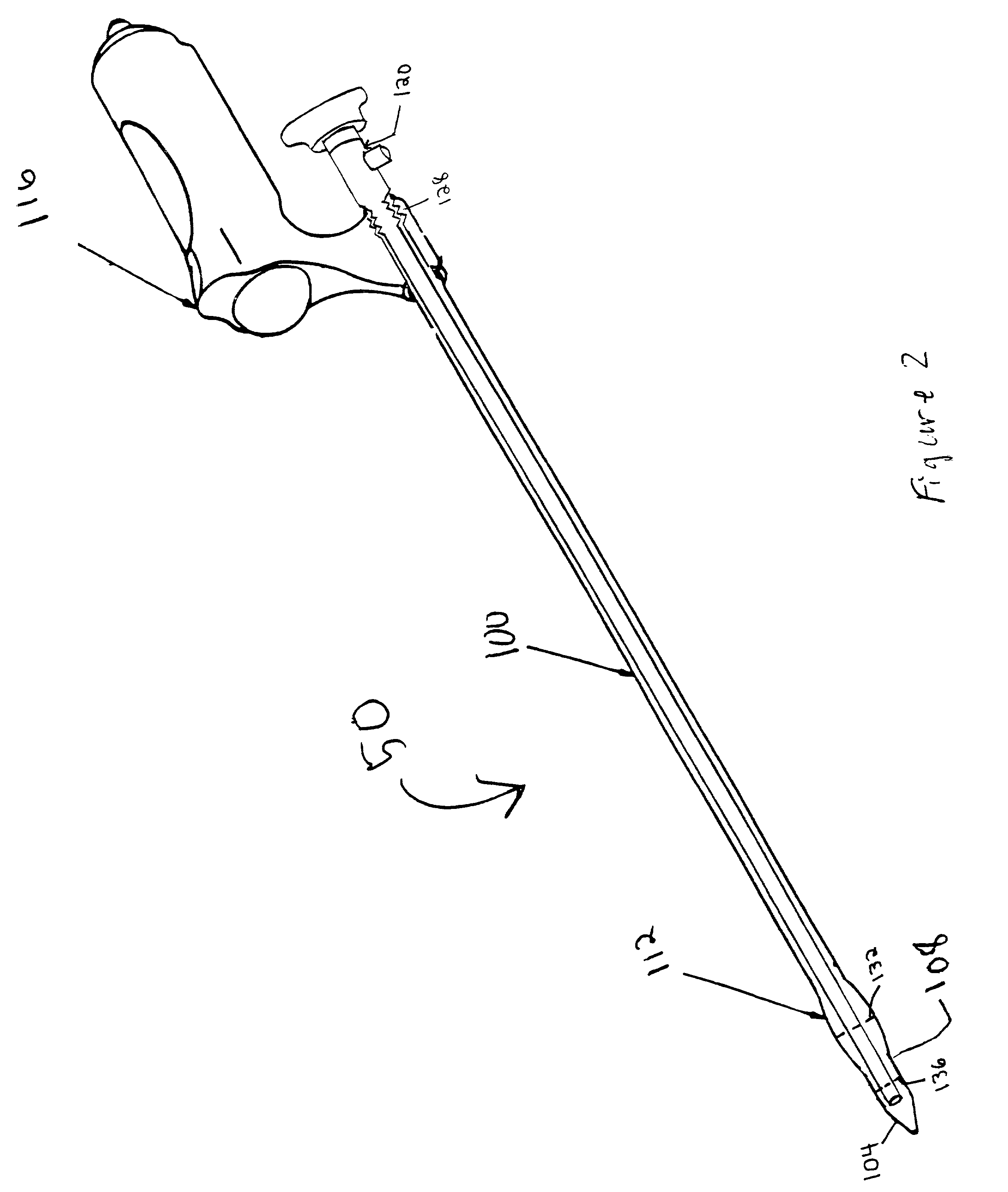
[0025]FIG. 2 illustrates a cut-away side sectional view of tissue detector 50. As shown, the distal end of cannula 100 has an outer diameter or dimension 136, and the dilating element 112 has an outer dimension 132 which is greater than the diameter 136. The proximal p...


PUM


Abstract

Surgical apparatus and method includes a cannula that houses an endoscope and supports a dilating element near a distal end of the cannula. The dilating element has a dimension which is greater than the diameter of the cannula for enlarging a surgical cavity in tissue as the cannula is advanced through tissue at a surgical site to provide working space adjacent a target vessel within which surgical instruments may be conveniently manipulated. The dilating element of oval sided shape permits surrounding tissue to be pushed away or otherwise displaced away from the target vessel atraumatically. A locking mechanism is disposed on the cannula, which accepts a succession of mating dilating elements of progressively larger dimensions for successive insertion and enlargement of a surgical cavity as required. In one embodiment, the dilating element is made of rigid plastic, and in another embodiment, the dilating element is made of resilient material that may be confined within a retractable sheath which, in the extended position, encases and compresses the dilating element to a smaller dimension and which, in a retracted position, allows the dilating element to resiliently expand and enlarge the surgical cavity.

Description

[0001]This is a continuation of application Ser. No. 09 / 133,136 filed on Aug. 12, 1998, now abandoned, which is incorporated by reference herein in its entirety.FIELD OF THE INVENTION[0002]The present invention relates to the field of surgical apparatus, and more particularly to endoscopic vessel isolators.BACKGROUND OF THE INVENTION[0003]During surgical harvesting of vessels, a target vessel is exposed, tributaries are ligated and transected, and the vessel is harvested. In order to view the vessel, a cannula housing an endoscope is inserted into a surgical cavity to visualize the adventitial layer of a target vessel. The vessel is tracked by advancing the cannula along the path of the vessel while bluntly dissecting the cavity as the cannula is advanced. Upon viewing a side branch or tributary of the vessel, a surgical tool is inserted into the surgical cavity to cauterize and sever the side branch. The endoscope remains in the surgical cavity during this process to allow the surg...

Claims


Application Information

Patent Timeline
Patent Type & Authority Patents(United States)
IPC IPC(8): A61B17/00A61B17/32
CPCA61B17/00008A61B17/320016A61M29/02A61B17/32A61B2017/320048A61B18/1482A61B17/3201A61B18/1445A61B2018/00428A61B2018/1412A61B2017/320064A61B2018/1452A61F2/062A61B18/148A61B2018/00404A61B2018/00595
Inventor CHIN, ALBERT K.
Owner MAQUET CARDIOVASCULAR LLC
Why Eureka
Try Eureka