
Low cost liquid cooling

a liquid cooling and low cost technology, applied in the direction of electrical apparatus casings/cabinets/drawers, instruments, semiconductor/solid-state device details, etc., can solve the problems of high air speed, complex cooling of these systems, and increase in power consumption per unit volume of computers

Inactive Publication Date: 2011-06-14
IBM CORP
View PDF12 Cites 38 Cited by
  • Summary
  • Abstract
  • Description
  • Claims
  • Application Information

AI Technical Summary

Benefits of technology

The present invention provides a system for cooling processor assembly that overcomes the shortcomings of the prior art. The system includes a cooling plate with internal manifolds for a liquid coolant distribution, printed circuit boards with heat emitting electronic components, and housings for each PCB with a heat sink covering the electronic components. The PCBs are fixed onto the cooling plate by clamps on the housing, allowing for hot plugging of the PCB onto the cooling plate without interrupting the cooling process. The system also includes a method for cooling processor assembly by positioning the PCBs on the cooling plate and fixing them with the housing using a clamping mechanism. The invention provides improved thermal coupling between the PCBs and the cooling plate, resulting in better cooling efficiency.

Problems solved by technology

As computers grow in speed and shrink in size, power consumed within the computer per unit volume (power density) increases dramatically.
However, there are also disadvantages.
One such disadvantage consists in the fact that cooling of these systems is very much complicated due to the amount of CPUs per rack.
Due to the enormous generation of heat, air outlet temperatures of more than 50° C. with extremely high air speeds and noise emission will result.
But as the heat is finally transported to air, this technology has no principal advantages over direct air cooling.
However, this method requires a high energy and special air conditioning systems.
Such alternative has the advantage to allow hot swapping but requires very technically challenging architecture to combine a secondary cooling circuit on each PCB which makes such solution very cost-intensive.
Furthermore, defective pipes or hoses can cause outflow of water that leads to damages to the server (breakdown of the processor and damage to the electronic device, respectively).
Such solution is based on the use of heat pipes which are very cost-intensive.
Furthermore, the disclosed coupling between the first and the second heat sink seems not to be reliable in a satisfactory way.

Method used


Image

  • Low cost liquid cooling
  • Low cost liquid cooling
  • Low cost liquid cooling

Examples


Embodiment Construction

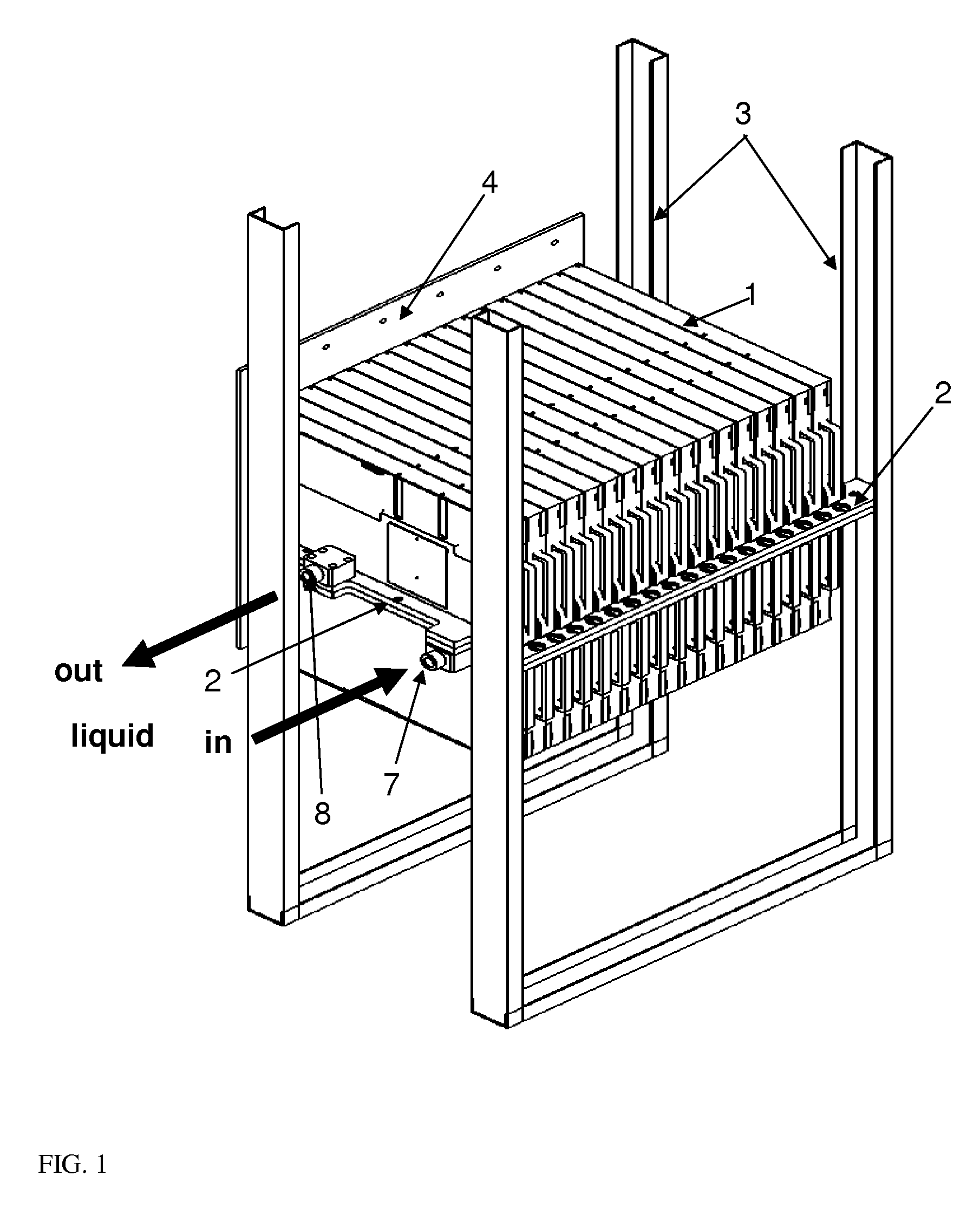
[0029]The present invention relates to a system for cooling processor assembly. For simplification of the description of the present invention a processor node of a super computer or main frame is taken as an example of a processor assembly. Such processor node also called in a server environment blade server consists of a PCB with a plurality of heat emitting electronic components and some housing covering at least partly the heat emitting electronic components. The housing comprises a base portion to which are transferred the heat emitted by the electronic components usual when activated. Such base portion is used to be positioned on a cooling plate in such a way that a plurality of similar processor nodes with their base portion can be fixed in series.

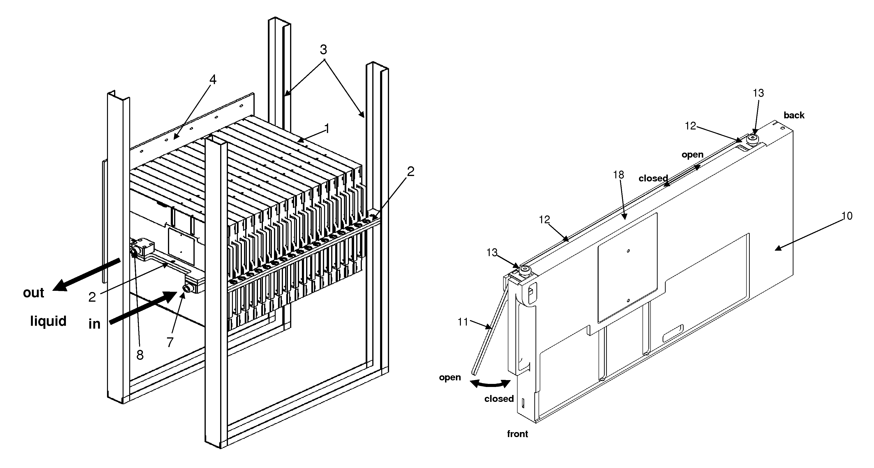
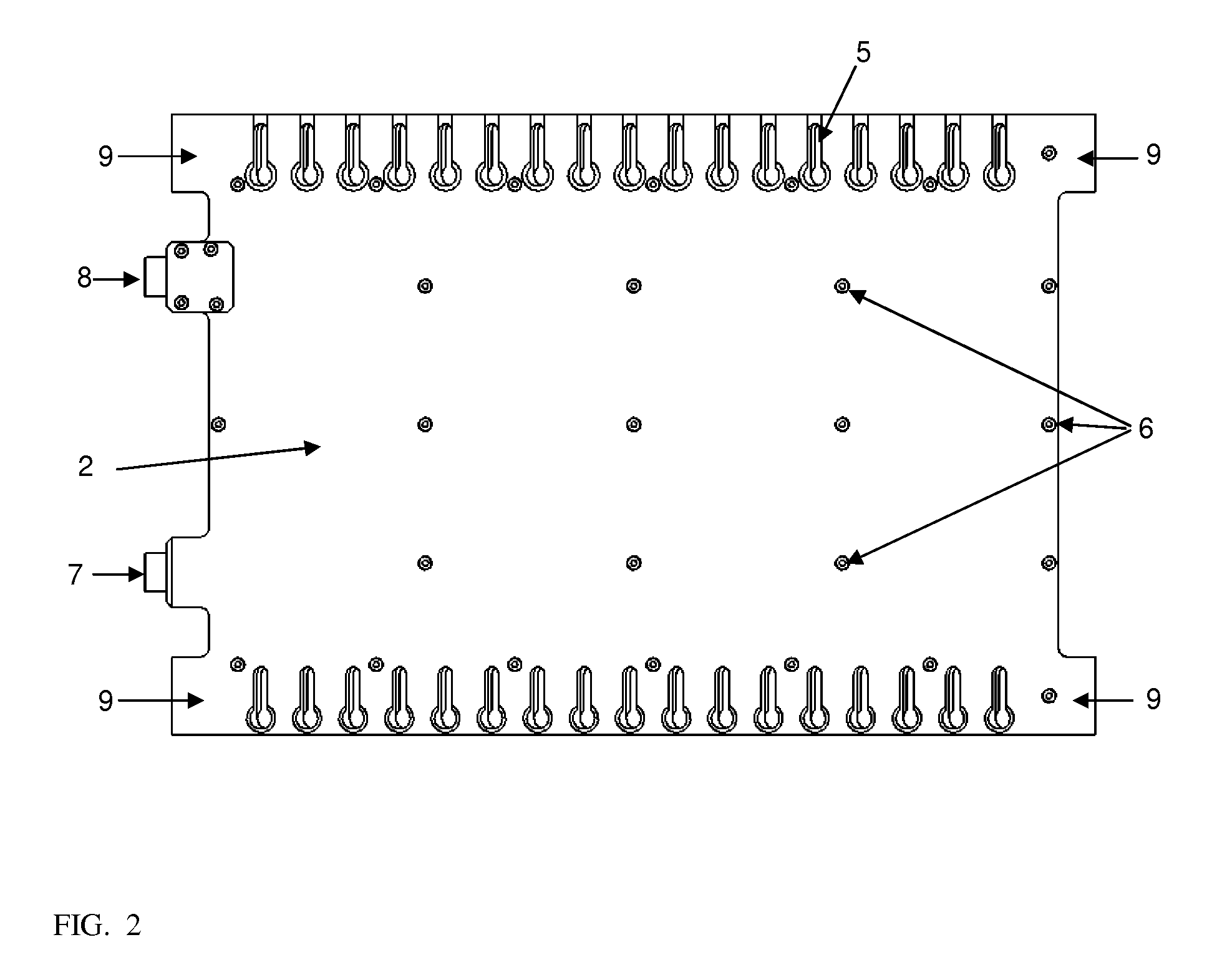
[0030]FIG. 1 shows a part view of a supercomputer with a frame or rack made out of profiles 3 or hollow structural sections on which is fixed a cooling plate 2 according to the invention. A plurality of processor nodes 1 with their ...


PUM


Abstract

A system for cooling processor assembly is disclosed which comprises printed circuit boards (PCB) with a plurality of heat emitting electronic components, and a housing for each PCB with a heat sink covering at least partly the heat emitting electronic components. The housing comprises a base portion to which are transferred heat emitted by the electronic components. Furthermore, the system for cooling processor comprises a cooling plate on which are fixed in series the different PCBs by directly positioning the base portion of the housings onto the cooling plate. The housings for each PCB system include at their base portions clamps to be inserted into corresponding guiding holes of the cooling plate when a PCB together with its housing is positioned onto the cooling plate at a specific therefor dedicated place defined by the guiding holes. Advantageously, the PCB together with its housing is pressed against the cooling plate alongside the base portion when fixed onto the cooling plate allowing thermal coupling between the housing and the cooling plate and a hot plugging of the PCB onto the cooling plate without requiring interrupting the cooling process applied to the cooling plate.

Description

TECHNICAL FIELD[0001]This invention relates to a system for cooling processor assembly comprising printed circuit boards (PCB) with a plurality of heat emitting electronic components. It is also related to an electronics rack with a plurality of such systems for cooling processor assembly and a method of cooling processor assembly.BACKGROUND OF THE INVENTION[0002]As computers grow in speed and shrink in size, power consumed within the computer per unit volume (power density) increases dramatically. Thus, it becomes essential to dissipate the heat generated by electronic components within the computer during operation to ensure that the components remain within their normal operating temperature ranges, since otherwise the components will fail immediately or will have a significantly shorter lifetime.[0003]One of the most common techniques of dissipating heat from a component of a computer is to directly apply a relatively high velocity air flow across the surface of the component an...

Claims


Application Information

Patent Timeline
Patent Type & Authority Patents(United States)
IPC IPC(8): H05K7/20F28F7/00
CPCG06F1/20H01L23/473H05K7/20772H01L2924/0002H01L2924/00
Inventor GOLDRIAN, GOTTFRIED A.RIES, MANFRED
Owner IBM CORP
Learn More