Fuel pressure sensor/sensor mount assembly, fuel injection apparatus, and pressure sensing apparatus

a technology of fuel pressure sensor and sensor mount, which is applied in the direction of mechanical equipment, machines/engines, instruments, etc., can solve the problems of increasing the size of the fuel injector in a direction, reducing the accuracy of determining such a pressure change, and not ensuring the desired accuracy in determining the fuel pressure change. , to achieve the effect of reducing the amount of electrical nose added

Inactive Publication Date: 2011-06-21
DENSO CORP
View PDF37 Cites 23 Cited by
  • Summary
  • Abstract
  • Description
  • Claims
  • Application Information

AI Technical Summary

Benefits of technology

[0020]The connector is, as described above, disposed between the fuel injector and the fuel pipe, thus eliminating the need for a branch path diverging from a fuel flow path extending in the fuel injector. This permits the size of the fuel injector to be minimized and improves the mountability of the fuel injector in the internal combustion engine.
[0025]The connector may be designed to be fastened threadably to the fuel injector and the fuel pipe. The direction in which the connector is fastened threadably to the fuel injector is oriented to traverse the direction in which the connector is fastened threadably to the fuel pipe. This avoids undesirable rotation of the connector following rotation of the fuel pipe when the fuel pipe is disconnected from the connector.
[0033]According to the third aspect of the invention, there is a provided a fuel injection apparatus which comprises: (a) an injector body which has a fuel flow path to which fuel is supplied from an external fuel induction pipe and a spray hole which communicates with the fuel flow path and from which at least a portion of the fuel is sprayed; (b) an inlet body which is designed to be separate from the injector body and secured to the injector body, the inlet body having formed therein a fuel inlet path communicating between the external fuel induction pipe and the fuel flow path of the injector body; and (c) a fuel pressure sensor which is installed in the inlet body and includes a diaphragm which is to be deformed in response to pressure of the fuel flowing through the fuel inlet path and a sensing element which produces a signal as a function of a degree of deformation of the diaphragm. This structure permits the fuel pressure sensor to be diagnosed in operation thereof before the inlet body is secured to the injector body. If a failure in operation of the fuel pressure sensor is found, it may be replaced easily, thus improving the fabrication yield of the fuel injection apparatus.
[0035]The diaphragm may have a flat surface on which the sensing element is mounted. The plane of the flat surface is oriented at an angle greater than or equal to 0° and smaller than 90° to an axial direction of the injector body. This avoids the addition of vibrations arising from the combustion of fuel in the engine to the output of the fuel pressure sensor.
[0036]The plane of the flat surface of the diaphragm may alternatively be oriented at an angle greater than or equal to 0° and smaller than or equal to 75° to the axial direction of the injector body. This causes the vibrations to be reduced by 0 to 0.95 times in degree, thus resulting in a decrease in electrical nose added to the output of the fuel pressure sensor.
[0045]According to the fourth aspect of the invention, there is provided a pressure sensing apparatus for use in a fuel injection system working to spray fuel which comprises: (a) an inlet body including a fuel inlet path through which fuel flows, an open hole and a recess, the open hole extending from an outer wall of the inlet body into the fuel inlet path to define a branch path diverging from the fuel inlet path, the recess being formed to occupy an area of the outer wall of the inlet body in which the open hole is formed; (b) a hollow cylindrical stem having an open end communicating with the branch path and a closed end which is opposite the open end and which defines a diaphragm, the diaphragm having opposed first and second surfaces, the first surface facing the fuel inlet path; and (c) a fuel pressure sensor mounted on the second surface of the diaphragm. The pressure sensor produces a signal as a function of a degree of deformation of the diaphragm arising from exertion of pressure of the fuel. The recess of the inlet body is so formed in the inlet body that an outermost portion of one of the fuel pressure sensor and the stem in a radial direction of the inlet body is located radially inside an outermost portion of the outer wall of the inlet body which defines the recess. This avoids the removal of or physical damage to the fuel pressure sensor when the inlet body is fixed to the injector body.

Problems solved by technology

For instance, in the case where a change in pressure of the fuel arising from the spraying of the fuel from the fuel injector (which will also be referred to as a fuel pressure change below) is measured using a fuel pressure sensor installed directly in a common rail (i.e., a fuel accumulator), it will be somewhat absorbed within the common rail, thus resulting in a decrease in accuracy in determining such a pressure change.
The use of the pressure sensor, as disclosed in the above publication, installed in the joint between the common rail and the high-pressure pipe, therefore, does not ensure the desired accuracy in determining the fuel pressure change.
Such installation, however, has been found to pose the problems, as discussed below.
This structure, however, results in an increase in size of the fuel injector in a direction toward the branch path.
It is, however, impossible for the structures, as disclosed in the above second to fourth publications, to measure the pressure of fuel inputted directly into the fuel injector.
Therefore, in the case where the outer wall of the body of the fuel injector is ground to form the recess, it is difficult to control the thickness of the diaphragm (i.e., the bottom of the recess).
The above problems, therefore, become more serious in such a type of fuel injectors.
This causes the vibrations to be added as an electrical noise to the output of the fuel pressure sensor.

Method used


Image

  • Fuel pressure sensor/sensor mount assembly, fuel injection apparatus, and pressure sensing apparatus
  • Fuel pressure sensor/sensor mount assembly, fuel injection apparatus, and pressure sensing apparatus
  • Fuel pressure sensor/sensor mount assembly, fuel injection apparatus, and pressure sensing apparatus

Examples


first embodiment

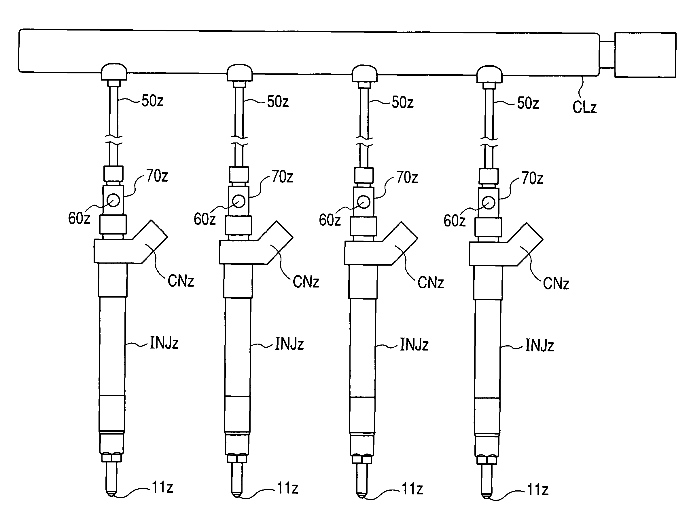
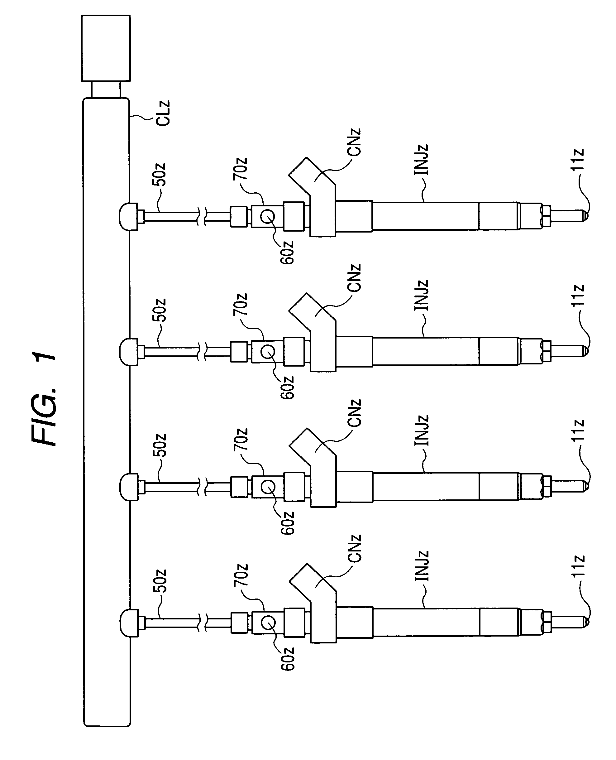
[0122]The above described first embodiment offers the following beneficial effect.[0123]1) The connector 70z is disposed between the high-pressure port 43z of the injector INJz and the high-pressure pipe 50z. The fuel pressure sensor 60z is installed in the connector 70z to measure the pressure of fuel supplied to the fuel injector INJz. This enables a change in pressure of the fuel arising from the spraying of the fuel from the fuel injector INJz to be monitored without installation of the fuel pressure sensor 60z within the fuel injector INJz. The connector 70z in which the fuel pressure sensor 60z is installed occupies the part of space between the fuel injectors INJz and the common rail CLz, thus eliminating the need for an increase in radial size of the fuel injectors INJz caused by the installation of the fuel pressure sensors 60z in the fuel injectors INJz and also facilitating the ease of installation of the fuel injectors INJz in the cylinder head E2z. [0124]2) The connecto...

third embodiment

[0143]The pipe nut 720z has the center hole 72bz greater in diameter than that in the third embodiment to define a conductive outlet through which the conductive wire 63z of the fuel pressure sensor 60z (i.e., the strain gauge 620z) extends outside the pipe nut 720z through the gasket P1z. The pipe nut 720z may alternatively be designed to have formed in a side wall thereof a conductive outlet hole through which the conductive wire 63z passes.

[0144]The fifth embodiment of the invention will be described below with reference to FIG. 7 which is a modification of the first embodiment. The same reference numbers, as employed in the first embodiment, will refer to the same parts, and explanation thereof in detail will be omitted here.

[0145]In order to avoid the rotation of the connector 701z following the rotation of the high-pressure pipe 50z when the high-pressure pipe 50z is removed from the connector 701z, the third embodiment is designed to have the connector 701z retained between t...

seventh embodiment

[0150]the invention will be described below with reference to FIG. 9. The same reference numbers, as employed in the above embodiments, will refer to the same parts, and explanation thereof in detail will be omitted here.

[0151]The fuel injectors INJz of the above embodiments are designed to have the high-pressure port 43z extending in the axial direction J1z thereof, but, the high-pressure port 43z of this embodiment is designed to have an axial direction J3z extending diagonally to the axial direction J1z of the fuel injector INJz. The electric connector CNz is, unlike the first embodiment, disposed on the end of the injector body 4z along the axial direction J1z (i.e., the longitudinal center line) of the injector body 4z.


PUM


Abstract

A fuel pressure sensor / sensor mount assembly in which a fuel pressure sensor is so mounted as to exposed to a high-pressure fuel path through which fuel is supplied to a fuel injector, a fuel injection apparatus equipped with a built-in fuel pressure sensor, and a pressure sensing apparatus working to measure the pressure of fuel in a fuel injector are provided. The fuel pressure sensor / sensor mount assembly is disposed between the high-pressure fuel path and the fuel injector, thus permitting the size of the fuel injector to be minimized without sacrificing the accuracy in measuring the pressure of the fuel. The fuel injection apparatus and the a pressure sensing apparatus are designed to ensure desired accuracy in measuring the pressure of the fuel.

Description

CROSS REFERENCE TO RELATED DOCUMENT[0001]The present application claims the benefit of Japanese Patent Applications No. 2008-86989 filed on Mar. 28, 2008, No. 2008-239748 filed on Sep. 18, 2008, and No. 2008-106015 filed on Apr. 15, 2008, disclosures of which are incorporated herein by reference.BACKGROUND OF TUE INVENTION[0002]1. Technical Field of the Invention[0003]The present invention relates generally to a fuel pressure sensor / sensor mount assembly in which a fuel pressure sensor is so mounted as to exposed to a high-pressure fuel path through which fuel is supplied to a fuel injector, a fuel injection apparatus equipped with a fuel pressure sensor, and a pressure sensing apparatus working to measure the pressure of fuel in a fuel injector.[0004]2. Background Art[0005]In order to ensure the accuracy in controlling output torque of internal combustion engines and the quantity of exhaust emissions therefrom, it is essential to control a fuel injection mode such as the quantity o...

Claims


Application Information

Patent Timeline
Patent Type & Authority Patents(United States)
IPC IPC(8): G01M15/04
CPCF02M47/027F02M55/005G01L23/222F02M57/005F02M2200/24F02M61/14F02M65/003F02M2200/855
Inventor KONDO, JUNTAGUCHI, TOORUNARUSE, HIDEOYAMANAKA, AKITOSHI
Owner DENSO CORP
Why Eureka
Try Eureka