
Image-carrier protecting agent, protecting-layer forming device, image forming method, image forming apparatus, and process cartridge

a protective agent and image carrier technology, applied in the direction of instruments, coatings, developers, etc., can solve the problems of image failure so-called image blur, image carrier wear and scratching, and preventing uniform charging of image carriers

Inactive Publication Date: 2011-06-28
RICOH KK
View PDF20 Cites 12 Cited by
  • Summary
  • Abstract
  • Description
  • Claims
  • Application Information

AI Technical Summary

Benefits of technology

The present invention provides a protecting agent for an image carrier that includes an organic compound having melting property and an organic compound particle having thermal decomposition property. The protecting agent has a melting temperature lower than the decomposition temperature of the organic compound particle and a volume ratio ranging from 99 / 1 to 50 / 50. The protecting agent is applied to the image carrier using a holding unit, a protecting-agent supplying unit, and a pressing-force applying unit. The invention also includes an image forming apparatus including the protecting agent and a fixing unit for fixing the visible image transferred onto the recording medium. The technical effect of the invention is to provide a protecting agent that can effectively protect the image carrier during image formation and transfer.

Problems solved by technology

If these residues are conveyed to a charging process without being removed, these residues prevent uniform charging on the image carrier.
The stress due to friction in the cleaning process of these stresses causes the image carrier to wear and to be scratched.
However, if a lubricant layer produced thereby repeatedly passes through the charging process, the stearic acid is decomposed and may eventually remain as zinc oxide on the surface of the image carrier and the surface of a charging unit.
Therefore, electrostatic charge on the image carrier cannot be retained under high humidity environment, and an electrostatic latent image becomes vague, which may cause image failure so-called image blur to occur.
However, an area occupied by each of higher alcohol molecules absorbed in the image carrier tends to increase, and the density of molecules absorbed in the image carrier per unit area (weight of absorbed molecules per unit area) is low.
Consequently, the electrical stress easily penetrates a protecting layer, and thus the effect to satisfactorily protect the image carrier cannot easily be obtained.
And the ionic dissociating compound is taken into the lubricant layer and the resistance of the lubricant layer is reduced under high humidity, which may cause image blur to occur.
However, because the lubricant layer itself is slippery, not only the large force is needed for its removal but also the large mechanical stress is applied to the image carrier upon the removal.
However, in the method of pressing an edge of a cleaning unit such as a rubber-made cleaning blade against the surface of the image carrier to clean the surface thereof, it becomes difficult to block the toner particles by the edge due to the shape and the particle size of the polymerized toner particles, which easily causes cleaning failure to occur, namely, residual toner components cannot satisfactorily be cleaned.
It is described in this proposal that if a pressing force f is increased when a counter-type cleaning blade is used, some trouble such as squeaking of the cleaning blade and a warp thereof occurs, and it is therefore necessary to set an upper limit as an experimental value.
Thus, it does not seem to improve the capability.
Therefore, even though the protection of the surface of the image carrier from the electrical stress in the charging process is extremely important to the longer operating life of the image carrier and the charging unit and to the stabilized image quality, appropriate studies on this matter have not been conducted until now, and at the present situation, this matter therefore still remains as an unsolved problem.

Method used


Image

  • Image-carrier protecting agent, protecting-layer forming device, image forming method, image forming apparatus, and process cartridge
  • Image-carrier protecting agent, protecting-layer forming device, image forming method, image forming apparatus, and process cartridge
  • Image-carrier protecting agent, protecting-layer forming device, image forming method, image forming apparatus, and process cartridge

Examples


example 1

[0307]Although examples of the present invention are explained below, the present invention is not limited by these examples.

[0308]Table 1 shows formulae of row materials of examples 1 to 20 according to the present invention.

[0309]Table 2 shows formulae of row materials of comparative examples 1 to 6 according to the present invention.

[0310]In both tables, material name abbreviations are as follows.

[0311]FRW: Fisher Tropsch wax

[0312]IPW: Isoparaffin wax

[0313]MCW: Microcrystalline wax

[0314]NPW: Normal paraffin wax

[0315]D-G: D-glucose dehydration-condensation product (average number of glucoses=90)

[0316]PMM: Polymethyl methacrylate (average molecular weight=1500)

[0317]MSG: Glyceryl monostearate

[0318]Preparation of Protecting Agent 1 for Image Carrier

[0319]The composition of protecting agent Formula 1 shown in table 1 was put into a glass container with a lid, and melted and dispersed while being stirred by a hot stirrer in which temperature was controlled to 160° C.

[0320]The melted c...

example 21

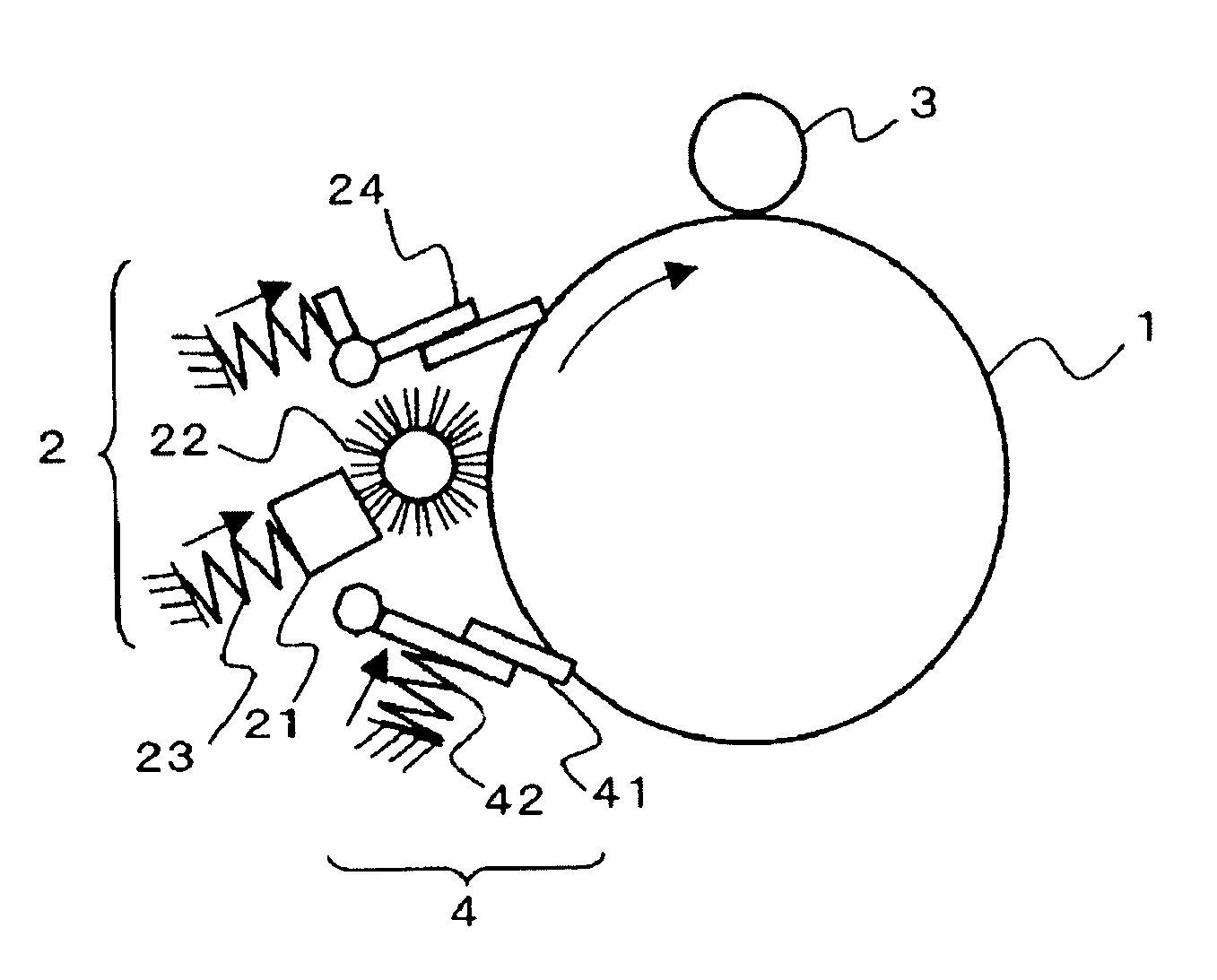
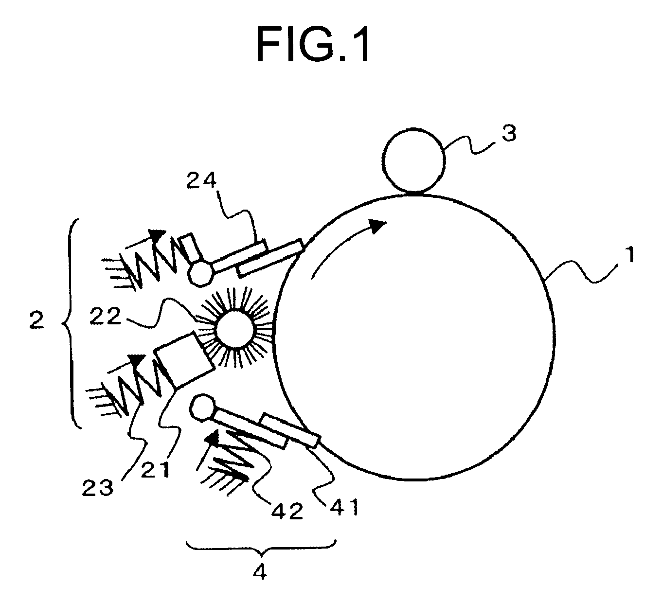
[0330]A process cartridge having the protecting-layer forming device using the protecting agent 1 according to the example 1 was prepared in the following manner. A transfer device, a counter-type cleaning blade, a brush-shaped protecting-agent supplying unit, a trailing-blade type protecting-layer forming unit are arranged in this order from the upstream side around an image carrier (photoconductor). More specifically, the image carrier has a surface layer of which surface contains thermosetting resin (thermal radical reaction type polyfunctional acrylic resin) and of which thickness is 5 micrometers.

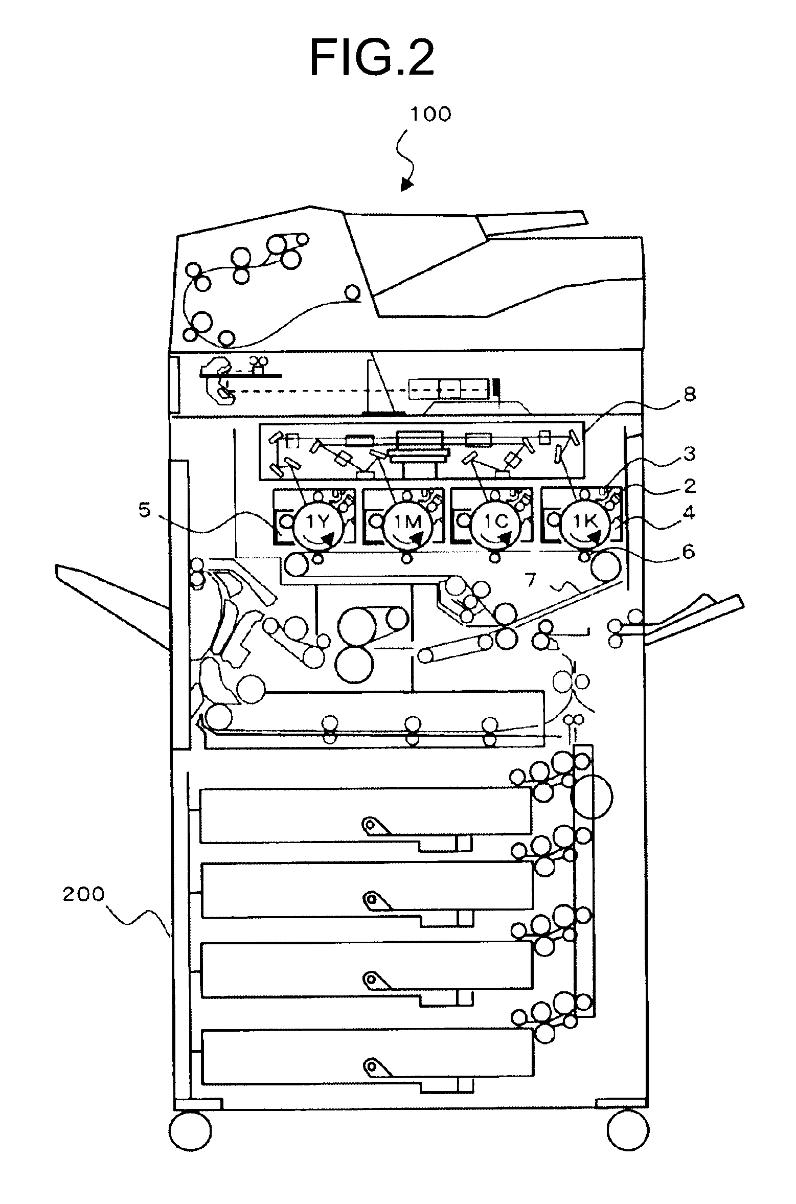
[0331]The obtained process cartridge was set in an image forming apparatus (Color multifunction product (MFP): imagio Neo C600 manufactured by RICOH COMPANY, LTD) which was modified so that the process cartridge was able to be incorporated therein). A test on continuous printing of images was conducted by using the image forming apparatus in such a manner that an A4-size document havin...

examples 22 to 40

[0364]The configuration according to the example 21 was not changed except for the protecting agents 2 to 20 used instead of the protecting agent 1, and evaluation was made in the same manner as that of the example 21.

[0365]The evaluation results of the image quality and results as to whether any foreign matter was fixed to the protecting agent are shown in the table 4 and the table 5, while the observation results on how the units were degraded are shown in the table 6.

[0366]It is noted that the paper passing test was conducted up to 500,000 sheets in total by using the image forming apparatuses according to examples 21, 22, and 23. As a result, the images were not affected at all, and respective degradations of the image carrier, the cleaning unit, and the charging unit were hardly found.


PUM


Abstract

A protecting layer is formed on a surface of an image carrier with a protecting agent that contains at least an organic compound having melting property of which penetration at 25° C. ranges from 3 millimeters to 30 millimeters, and organic compound particles having thermal decomposition property of which a weight average particle size ranges from 2 micrometers to 20 micrometers. A melting temperature of the organic compound is lower than a decomposition temperature of the organic compound particles, and a volume ratio of the organic compound to the organic compound particles ranges from 99 / 1 to 50 / 50.

Description

CROSS-REFERENCE TO RELATED APPLICATIONS[0001]The present application claims priority to and incorporates by reference the entire contents of Japanese priority document 2006-333583 filed in Japan on Dec. 11, 2006.BACKGROUND OF THE INVENTION[0002]1. Field of the Invention[0003]The present invention relates to a technology for protecting the surface of an image carrier used to form an electrophotographic image by using a protecting agent for the image carrier.[0004]2. Description of the Related Art[0005]Conventionally, image formation based on an electrophotographic system is implemented by forming an electrostatic latent image on an image carrier that has a photoconductive layer containing a photoconductive material or the like, and attracting charged toner to the electrostatic latent image to form a visible image. The visible image is transferred to a recording medium such as a sheet of paper and is fixed on the recording medium by heat, pressure, or solvent gas, and an output image ...

Claims


Application Information

Patent Timeline
Patent Type & Authority Patents(United States)
IPC IPC(8): G03G21/00
CPCG03G5/14708G03G2221/1609
Inventor YAMASHITA, MASAHIDENAKAI, HIROSHIIIO, MASATOTANAKA, SHINYAOZAKI, NAOYUKI
Owner RICOH KK
Learn More