Reactor cleaning apparatus

a technology for cleaning apparatus and reactors, applied in lighting and heating apparatus, cleaning using liquids, furnaces, etc., can solve the problems of inability to completely remove deposits, difficult to spray high-speed jet streams, and inability to proceed with hydrolysis of silicon deposits, etc., to achieve efficient and reliable removal

Active Publication Date: 2011-07-12
HIGH-PURITY SILICON CORP
View PDF15 Cites 0 Cited by
  • Summary
  • Abstract
  • Description
  • Claims
  • Application Information

AI Technical Summary

Benefits of technology

[0008]The present invention was made in view of such a problem, and an object thereof is to provide a reactor cleaning apparatus capable of easily and reliably removing deposits and cleaning water of an inner wall surface in a polycrystalline silicon reactor.
[0018]According to the reactor cleaning apparatus related to the invention, the cleaning water can be sprayed at high pressure three-dimensionally in various directions from an upper portion of the inner wall surface of the reactor to a lower portion thereof, and it becomes possible to directly spray the cleaning water uniformly throughout inner wall surface of the reactor. Additionally, since corrosive gas, such as hydrogen chloride is discharged to the outside of the system from the discharge hole, and the cleaning water makes to progress hydrolysis of the deposits and to remove the deposits as chemically stable silica, the treatment of the reactor after the cleaning is safe. In addition, since steam can be supplied into the bell jar of the reactor, remaining cleaning water is can be removed efficiently and reliably.

Problems solved by technology

Meanwhile, in the cleaning method described above, it is difficult to spray the high-speed jet stream uniformly throughout the inner wall surface of the reactor having irregularities, and it is impossible to perfectly remove the deposits.
Additionally, in the method of using CO2 pellets described Japanese Patent Publication No. 3167191, hydrolysis of the silicon deposits is not proceeded, hydrogen chloride might be generated when the reactor is opened.

Method used


Image

  • Reactor cleaning apparatus
  • Reactor cleaning apparatus
  • Reactor cleaning apparatus

Examples


Embodiment Construction

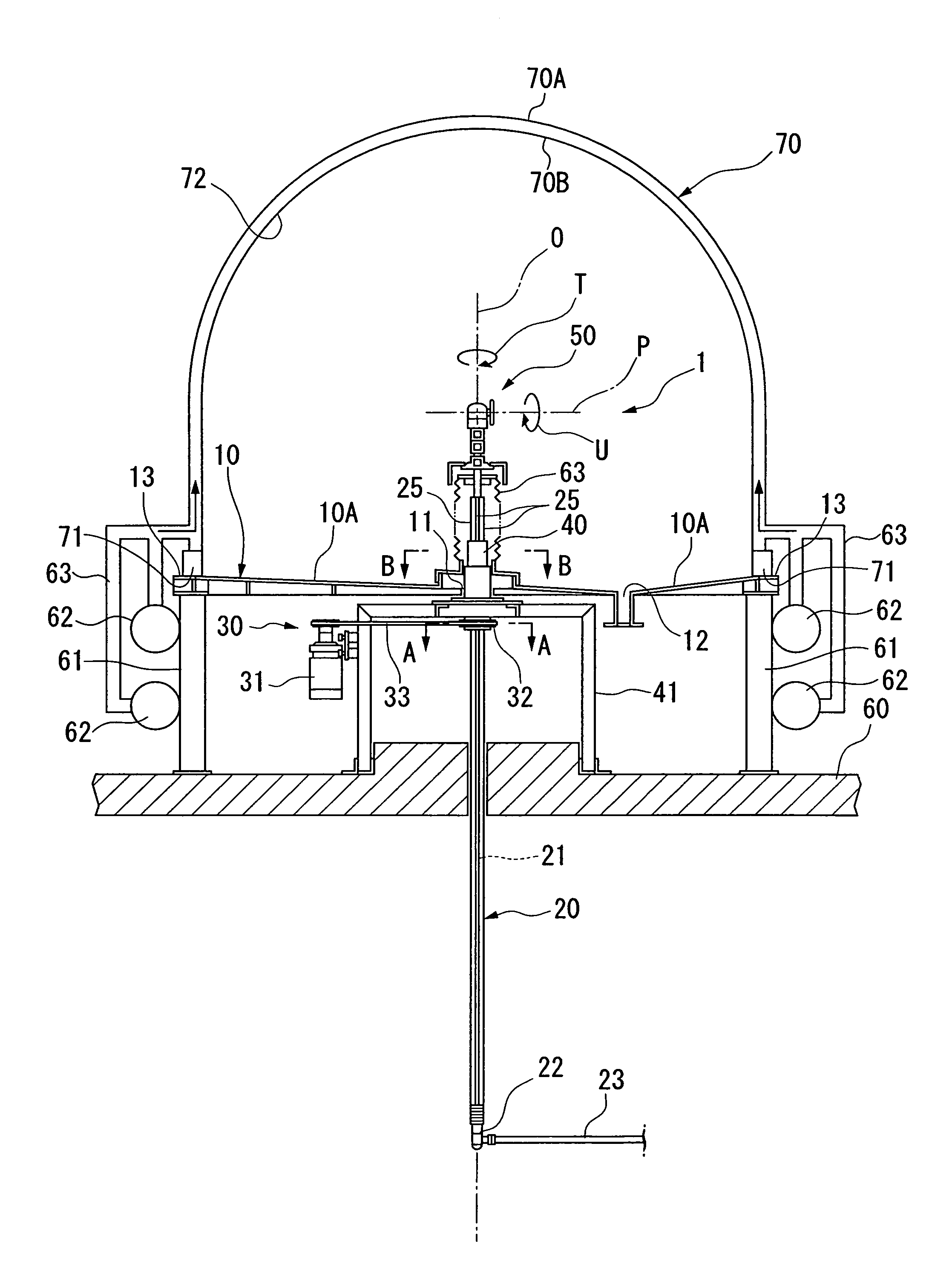
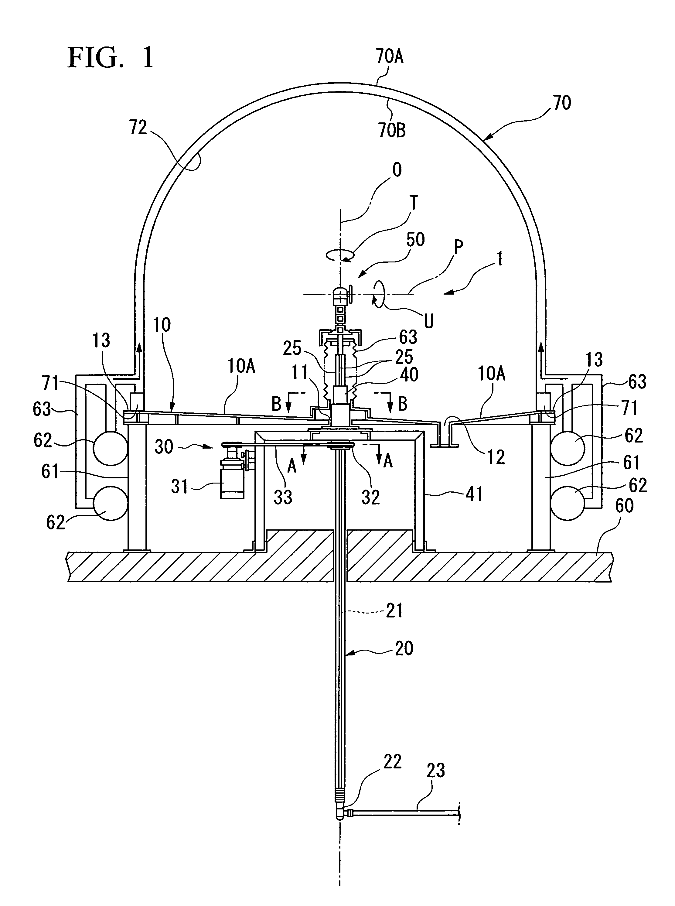
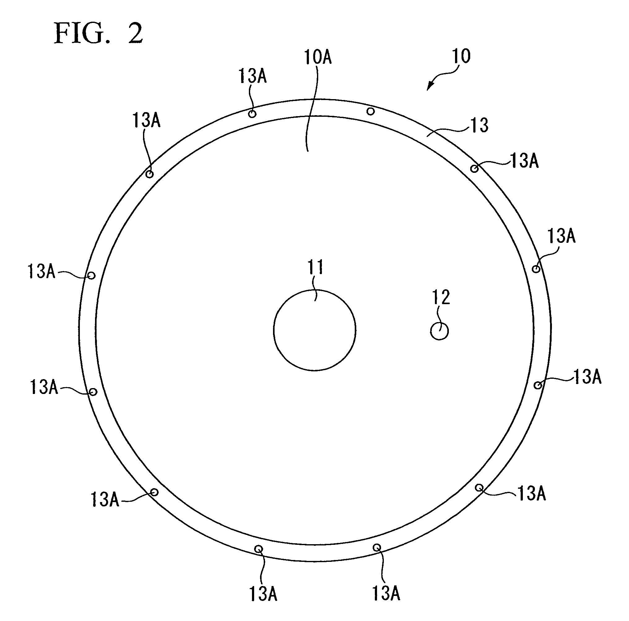
[0025]Hereinafter, a reactor cleaning apparatus that is an embodiment of the invention will be described in detail with reference to the drawings. FIG. 1 is a schematic configuration diagram of a reactor cleaning apparatus related to this embodiment, FIG. 2 is a plan view of a tray of the reactor cleaning apparatus related to this embodiment, FIG. 3 is an A-A sectional view in FIG. 1, FIG. 4 is a B-B sectional view in FIG. 1, and FIG. 5 is an enlarged view of a nozzle device of the reactor cleaning apparatus related to this embodiment. As shown in FIG. 1, the reactor cleaning apparatus 1 related to this embodiment generally includes a tray 10, a shaft 20, a drive mechanism 30, a fixed nut 40, and a nozzle device 50.

[0026]The tray 10 has a substantially disc-like shape, and is placed such that a bottom surface of an outer peripheral portion of the tray 10 is supported by a strut 61 suitably erected on a floor portion 60. As shown in FIG. 2, a through hole 11 is provided at a central ...


PUM

PropertyMeasurementUnit
pressureaaaaaaaaaa
pressureaaaaaaaaaa
rotationaaaaaaaaaa

Abstract

In a reactor cleaning apparatus 1 which cleans an inner wall surface 72 of a reactor 70 which generates polycrystalline silicon, a bell jar of the reactor 70 has a dual structure, a through hole 11 is formed along a vertical direction at a central portion of a substantially disc-like tray 10 placed in a horizontal state, a flange portion 13 in which an opening edge of the reactor 70 is placed is formed at an outer peripheral portion of the tray 10, a shaft 20 is provided through the through hole 11 of the tray 10 so as to be rotatable and movable in the vertical direction, a nozzle device 50 which sprays a cleaning water at high pressure in three-dimensional directions is provided at an upper end of the shaft 20, a drive mechanism 30 which rotates the shaft 20 and moves the shaft in the vertical direction is provided at a base end of the shaft 20, and steam piping 62 capable of supplying the steam within the bell jar of the reactor 70 is provided.

Description

BACKGROUND OF THE INVENTION[0001]1. Field of the Invention[0002]The present invention relates to a reactor cleaning apparatus which cleans an inner wall surface of a polycrystalline silicon reactor to be used when producing polycrystalline silicon using the Siemens method.[0003]Priority is claimed on Japanese Patent Application No. 2008-014967, filed Jan. 25, 2008, the content of which is incorporated herein by reference.[0004]2. Description of Related Art[0005]The Siemens method is known as a method of producing high-purity polycrystalline silicon to be used as a semiconductor material. This Siemens method is a production method of supplying a source gas which is a mixed gas of chlorosilane and hydrogens into contact with a heated silicon seed rod, and depositing the polycrystalline silicon which is generated by the thermal decomposition and hydrogen reducing reaction of a source gas, on the surface of the seed rod. As an apparatus which carries out this production method, a polycr...

Claims


Application Information

Patent Timeline
Patent Type & Authority Patents(United States)
IPC IPC(8): B08B3/02F27D25/00C01B33/02C01B33/035
CPCB08B3/02B08B3/04B08B3/08B08B9/28B08B9/34C23C14/564C23C16/4407C01B33/035F27D25/00
Inventor ENDOH, TOSHIHIDETEBAKARI, MASAYUKIISHII, TOSHIYUKISAKAGUCHI, MASAAKI
Owner HIGH-PURITY SILICON CORP
Why Eureka
Try Eureka