Asymmetric electronic parts

a technology of electronic parts and components, applied in the direction of electrical apparatus casings/cabinets/drawers, gaseous cathodes, coupling device connections, etc., can solve the problems of deformation of insert terminals, deformation of thin wall portions, and inability to fill thin wall portions with resin, etc., to achieve good mechanical properties and less warpage

Inactive Publication Date: 2011-07-19
POLYPLASTICS CO LTD
View PDF15 Cites 27 Cited by
  • Summary
  • Abstract
  • Description
  • Claims
  • Application Information

AI Technical Summary

Benefits of technology

[0009]A purpose of the present invention is to solve the above-described technological problems in the prior art, and to provide a material capable of forming a molded product having good mechanical properties, less warpage, and being excellent in any of the performance including heat resistance and flowability, even if the molded product is an asymmetric electronic parts.
[0010]The inventors of the present invention have conducted detail search and investigations to provide a material which achieves the above objectives, has excellent performance balance, and is suitable for molding an asymmetric electronic parts, and have found that an asymmetric electronic parts having excellent entire performance including warpage and heat resistance can be obtained by filling glass fibers having a specific length and not having longer than a specific length, and a specific plate-like filler in a liquid crystalline polymer, at a specific filling ratio, respectively, thereby having perfected the present invention.

Problems solved by technology

However, in recent years, by the further movement toward “lighter and more compact” connectors, there have arisen the problems of the generation of warpage after molding and during reflow-heating owing to the insufficient rigidity resulted from insufficient wall thickness of the molded product and to the internal stress generated by inserting metal terminals, which causes defective soldering with circuit-board.
That is, regarding the conventional strengthening only by glass fiber, there has arisen a problem in that a thin wall portion can not be filled with resin, or insert terminals are deformed due to pressure during molding by the increased additive amount of glass fiber for increasing the rigidity.
However, with the increased complexity in the shape of electronic parts in recent years, there has been required to provide asymmetric electronic parts that has no symmetry on any of the axial plane XY, axial plane YZ, and axial plane XZ of molded product.
In particular, since a memory module connector for notebook personal computer has a latch structure for connection and has a notch for positioning, the connector becomes a highly complex shape.
Different from the ordinary connector (symmetric electronic parts) which is symmetry on any of the axial plane XY, axial plane YZ, and axial plane XZ of molded product, the above asymmetric electronic parts have no symmetry, and thus the asymmetric electronic parts have a limitation in improving warpage from the standpoint of molding procedure.
Furthermore, an asymmetric electronic parts having a complex shape results in complex orientation of resin and filler within the molded product, which raises a problem of further difficulty in suppressing warpage by required higher flowability, and it impossible to obtain satisfactory product from the conventionally-proposed low-warpage material.

Method used


Image

  • Asymmetric electronic parts
  • Asymmetric electronic parts
  • Asymmetric electronic parts

Examples


examples

[0047]The present invention is described specifically in the following referring to the examples, but not limited to these examples. The determination of the physical properties and the tests in the examples were given as follows.

(1) Weight Average Fiber Length and Percentage of Fibrous Filler having 700 μm or Larger

[0048]Resin composition pellets of 5 g were heated to ash for 2 hours at 600° C. The ashing residue was fully dispersed in an aqueous solution of 5% polyethyolene glycol, which was then transferred on a petri dish using a dropper. The fibrous filler in the solution was observed by a microscope. At the same time, the weight average fiber length of the fibrous filler was measured using an image analyzer (LUZEX FS, manufactured by NIRECO Corporation). On conducting the image analysis, a subroutine was applied to separate overlapped fibers into individual ones, and thus to determine the length thereeach. The determination was given by excluding the fibrous filler having a fi...

example 6

[0095]The liquid crystalline polyester 5 was prepared under the same extrusion condition as that in Example 1 so that the liquid crystalline polyester may preliminarily contain 40% by weight of the glass fibers 3 described below. Then, pelletization was carried out similar to Example 3 except for using the liquid crystalline polyester 5 instead of the liquid crystalline polyester 3. From thus prepared pellets, the above test pieces were molded by an injection molding machine and evaluated. The result is shown in table 1.

[0096]Glass Fibers 3

[0097]ECS04T-790DE (chopped strand fibers of 6 μm of average fiber diameter and 3 mm of length), manufactured by Nippon Electric Glass Co., Ltd.

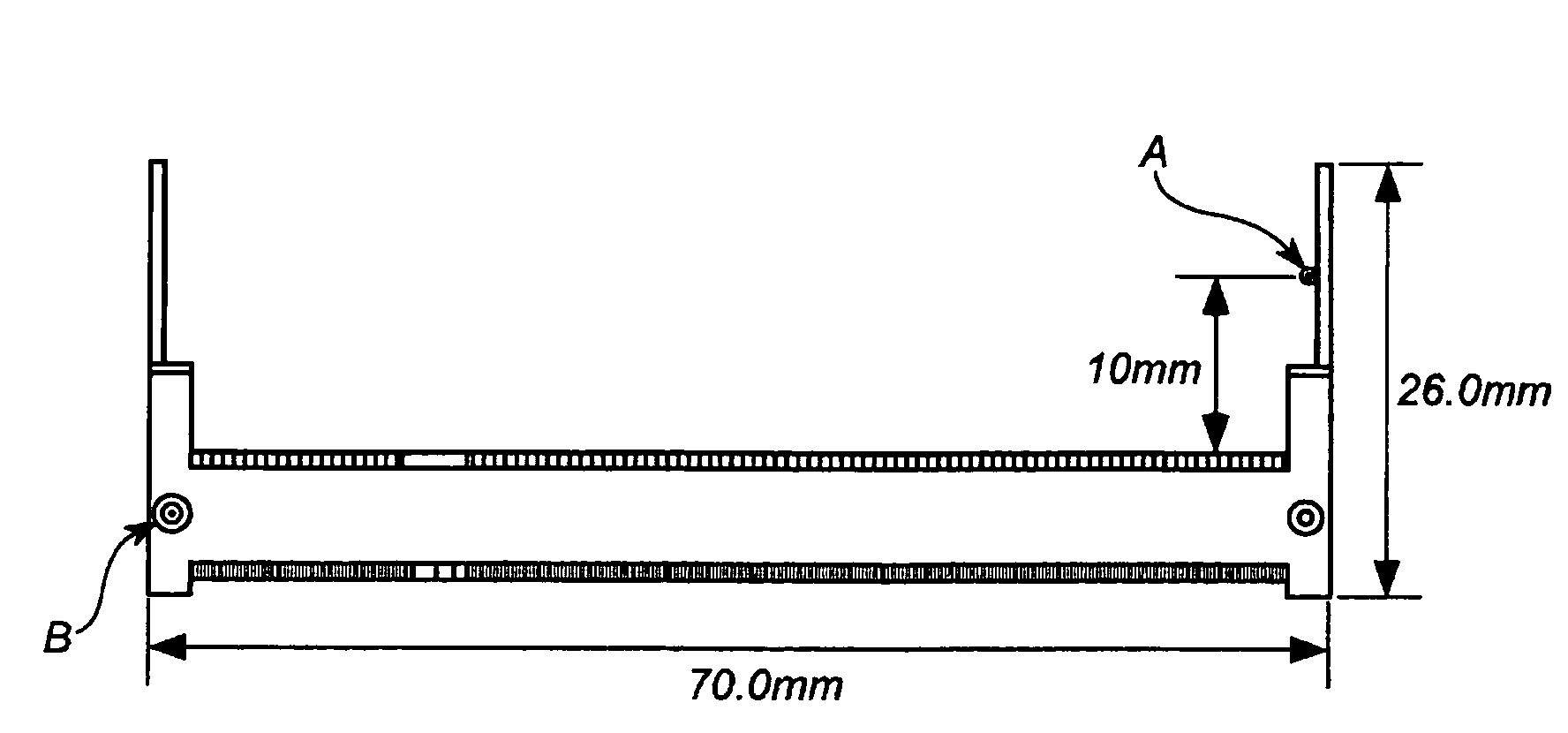
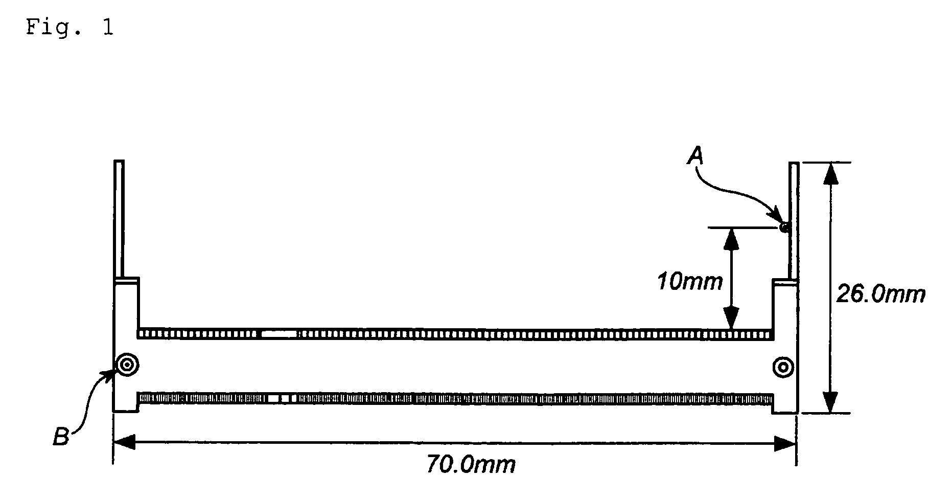
[0098]For the test pieces of Examples 1 to 3 and Example 6, the strength at the latch structural portion was measured. The result is given in Table 2.

[0099]

TABLE 1Comparative ExamplesExamples12345612Contents of Raw MaterialsUsed for ExtrusionLiquid Crystalline Polyester 1wt %27.520.032.532.550.050.0Liquid ...


PUM

PropertyMeasurementUnit
lengthaaaaaaaaaa
lengthaaaaaaaaaa
lengthaaaaaaaaaa

Abstract

Provided is a material capable of forming a molded product which has good mechanical properties with low warpage while being excellent in any of the performance including heat resistance and flowability, even if the molded product is an asymmetric electronic parts. Specifically, the asymmetric electronic parts is prepared by molding a liquid crystalline polymer composition comprising (A) a fibrous filler having an average fiber diameter within the range of 5 to 30 μm, having a weight average fiber length within the range of 250 to 350 μm, excluding 10 μm or shorter fiber length, and having a content of a fibrous filler being 700 μm or longer within the range of 5% by weight or less; and (B) a plate-like filler having an average particle size within the range of 0.5 to 200 μm, the total filling amount of (A) and (B) components in the composition being within the range of 40 to 60% by weight, the weight ratio of (A) component being within the range of 10 to 20% by weight, the weight ratio of (B) component being within the range of 30 to 40% by weight, the molded product having no symmetry in any of the axial plane XY, the axial plane YZ, and the axial plane XZ of the molded product.

Description

TECHNICAL FIELD[0001]The present invention relates to an asymmetric electronic parts for memory module connector, memory card socket, and the like.BACKGROUND ARTS[0002]Liquid crystalline polymers are known, among thermoplastic resins, as the materials having excellent dimensional accuracy, vibration damping property, and flowability, which generate very few burrs during molding, and very little gas. By utilizing these characteristics, the liquid crystalline polymers have been adopted in large quantities as the materials for varieties of electronic parts.[0003]In particular, with the increase in performance of electronic equipment in recent years, there have appeared the needs of the times for connectors having high heat resistance (the improvement in productivity supported by packaging technology), high density (multicore), and miniaturization. By taking advantage of the above liquid crystalline polymers, the liquid crystalline polymer compositions reinforced with glass fiber have b...

Claims


Application Information

Patent Timeline
Patent Type & Authority Patents(United States)
IPC IPC(8): H01R13/46C08K7/00C09K19/52C09K19/38C08L101/12
CPCC08K3/0033C08K7/14C08K3/013
Inventor FUKATSU, HIROKIKAYUKAWA, SEIJIOHSHIBA, HIROKAZUNISHIKAWA, RAITA
Owner POLYPLASTICS CO LTD
Why Eureka
Try Eureka