
Method and apparatus for treatment of contaminated liquid

a technology for contaminated liquid and treatment methods, applied in the direction of liquid displacement, multi-stage water/sewage treatment, separation processes, etc., can solve the problems of slowing down the processing capability of the treatment system, loosening of the material collected on the membrane surface, and clogging of the membrane, so as to facilitate the flow of liquid and achieve the effect of reducing the density of the sludge blanket, facilitating the flow of liquid, and occupying less spa

Inactive Publication Date: 2011-07-19
POWELL SCOTT W
View PDF95 Cites 23 Cited by
  • Summary
  • Abstract
  • Description
  • Claims
  • Application Information

AI Technical Summary

Benefits of technology

"The present invention provides a method and apparatus for treatment of contaminated liquids by using a combination of ultra-filtration and clarifier steps. The apparatus includes a tank with an ultra-filtration system and an electrocoagulation function integrated within it. The apparatus can be used in water treatment and wastewater treatment. The apparatus includes a sludge blanket that helps to remove solids from the liquid before it reaches the ultra-filtration unit, which increases the life of the ultra-filtration unit. The apparatus also includes a control system to maintain the sludge blanket at a desired level and can adjust the density of the sludge blanket to facilitate the flow of liquid through the solid mass. The apparatus provides a more efficient and cost-effective treatment for contaminated liquids."

Problems solved by technology

One particular limitation in the use of a reverse osmosis unit, as well as ultra-filtration units, is that the membranes will become clogged over time, and some reverse flow is required to cause a loosening of the material collected on the membrane surfaces.
The backwash requirement slows the processing capability of the treatment system.
This cleaning requirement further delays the operation of the waste treatment facility.

Method used


Image

  • Method and apparatus for treatment of contaminated liquid
  • Method and apparatus for treatment of contaminated liquid
  • Method and apparatus for treatment of contaminated liquid

Examples


Embodiment Construction

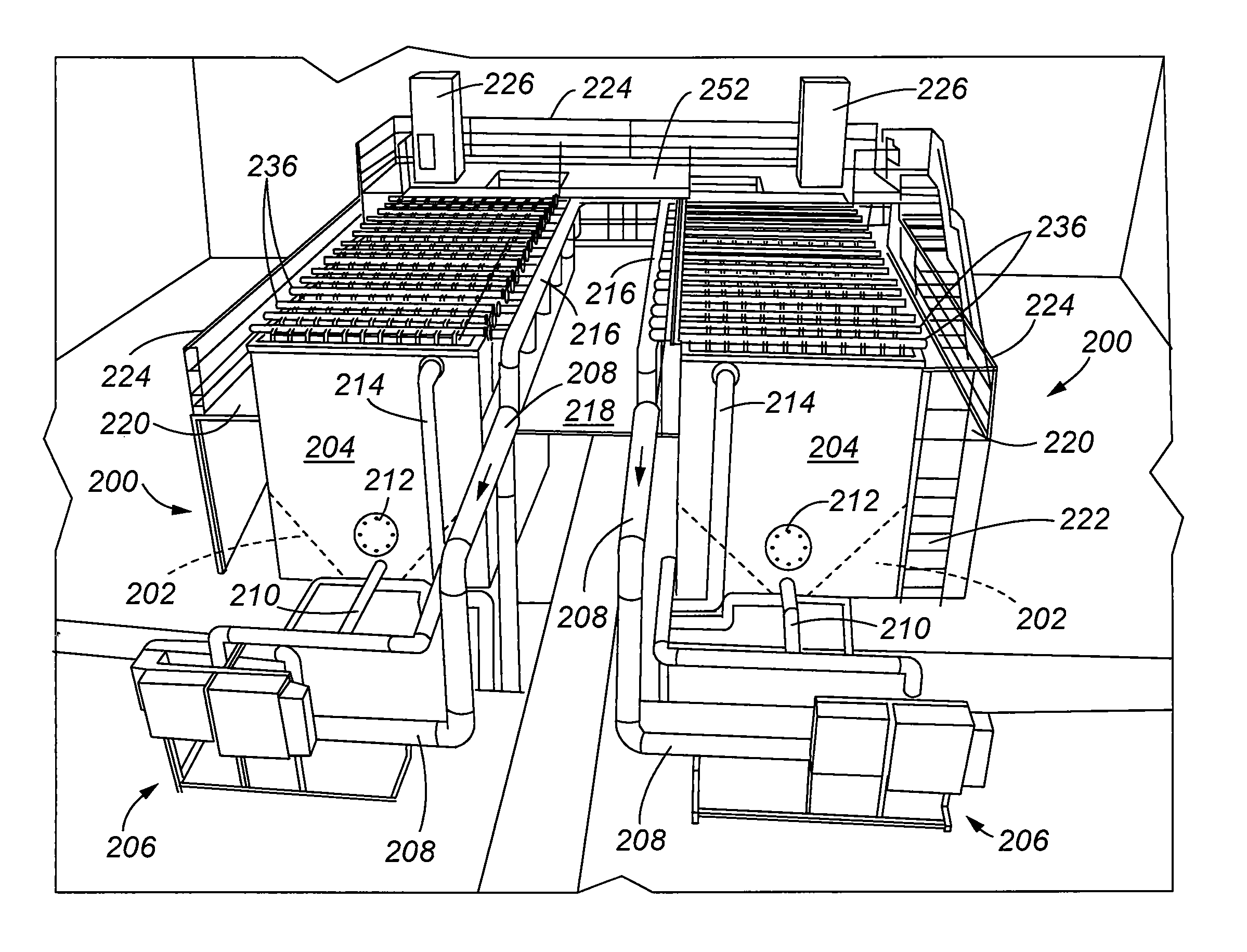
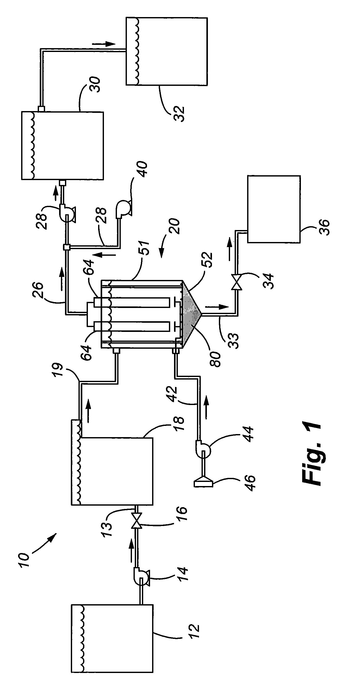
[0038]Referring to FIG. 1, a system 10 in accordance with the present invention is illustrated comprising a number of components that are used to provide treatment for the liquid, which may include water, or other liquids that are used in industrial and commercial purposes. The system 10 can be incorporated into yet a larger treatment system designed to specifically treat for removal of targeted contaminants. Thus, it shall be understood that the system 10 of the present invention can either be a stand-alone system, or can be incorporated within yet a larger treatment system.

[0039]FIG. 1 more specifically illustrates a first holding tank / reservoir 12 that provides the contaminated liquid to be treated. The liquid is conveyed to an electrocoagulation unit 18 by a pump 14 in which a control valve 16 regulates the flow of liquid through the conveying line 13. The electrocoagulation unit 18 may be conventional, such as the ones illustrated in the U.S. Pat. No. 7,211,185 entitled “METHOD...


PUM

PropertyMeasurementUnit
vacuum forceaaaaaaaaaa
chemicalaaaaaaaaaa
homogenousaaaaaaaaaa

Abstract

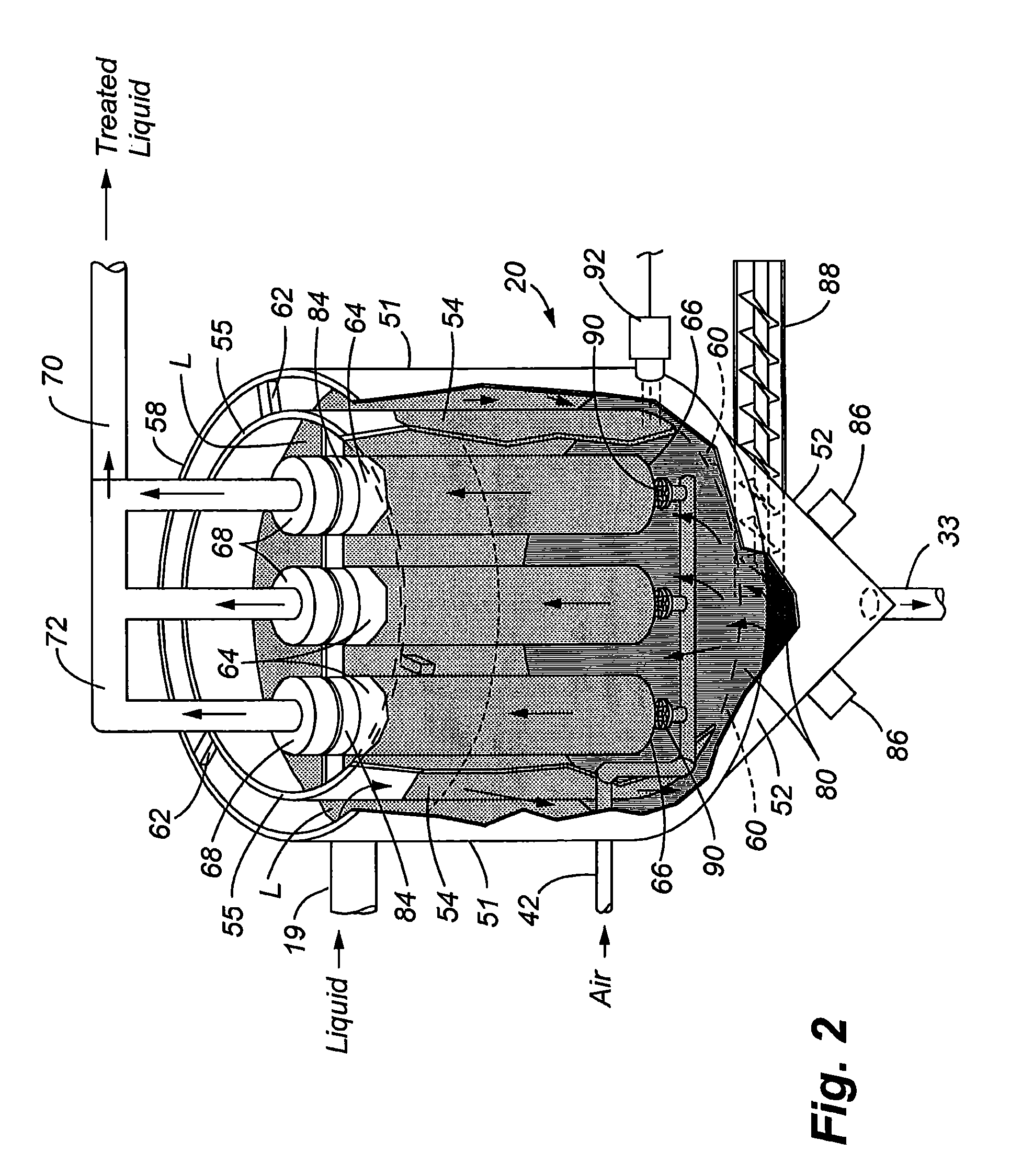
An apparatus includes integrated ultra-filtration and clarification, and an optional electrocoagulation capability. The apparatus comprises an outer tank, an inner casing, and a plurality of ultra-filtration filters contained within the inner casing. Clarification of liquid occurs in the gap between the casing and tank. Solid matter settles, and aggregates in the bottom portion of the tank. The accumulated solid material acts as a secondary filter by pre-filtering the liquid prior to contact with the ultra-filtration filters. Clarified liquid is retained in a chamber of the casing, and the clarified liquid is drawn through the ultra-filtration filters as initiated by a source of vacuum communicating with the ultra-filtration filters. Optionally, and upstream electrocoagulation unit and a downstream reverse osmosis unit are provided. Alternatively, the electrocoagulation function is provided by a plurality of reaction plates mounted to the interior sidewall of the tank.

Description

CROSS REFERENCES[0001]This application is a Continuation-In-Part of pending U.S. patent application Ser. No. 12 / 276,078, filed Nov. 21, 2008, entitled “METHOD AND APPARATUS FOR TREATMENT OF CONTAMINATED LIQUID” that is incorporated herein by reference in its entirety.FIELD OF THE INVENTION[0002]The present invention relates generally to systems and methods for treating liquids to remove contaminates such as suspended or dissolved solids. More particularly, the present invention relates to a system and method for treatment of a contaminated liquid in which an integrated clarifier and ultra-filtration apparatus are provided to improve the overall treatment process prior to a final treatment action, such as filtration by reverse osmosis.BACKGROUND OF THE INVENTION[0003]Wastewater treatment is the process of removing targeted contaminants from a wastewater stream. Wastewater treatment typically involves a series of treatment steps including chemical, biological and physical treatment me...

Claims


Application Information

Patent Timeline
Patent Type & Authority Patents(United States)
IPC IPC(8): B01D33/70C02F1/00B01D43/00C02F11/121
CPCC02F9/00C02F1/441C02F1/444C02F1/463C02F3/348C02F11/121C02F2101/308C02F2103/30
Inventor POWELL, SCOTT W.
Owner POWELL SCOTT W
Learn More