
Dual self-calibrating low-power oscillator system and operation

a low-power oscillator and self-calibration technology, applied in the field of oscillator design, can solve the problems of increasing the cost, affecting the behavior of such on-chip oscillators, and generally difficult to achieve the 250 ppm goal with a single oscillator, so as to achieve the effect of less power and reduced power consumption

Inactive Publication Date: 2011-07-19
QUALCOMM INC
View PDF1 Cites 10 Cited by
  • Summary
  • Abstract
  • Description
  • Claims
  • Application Information

AI Technical Summary

Benefits of technology

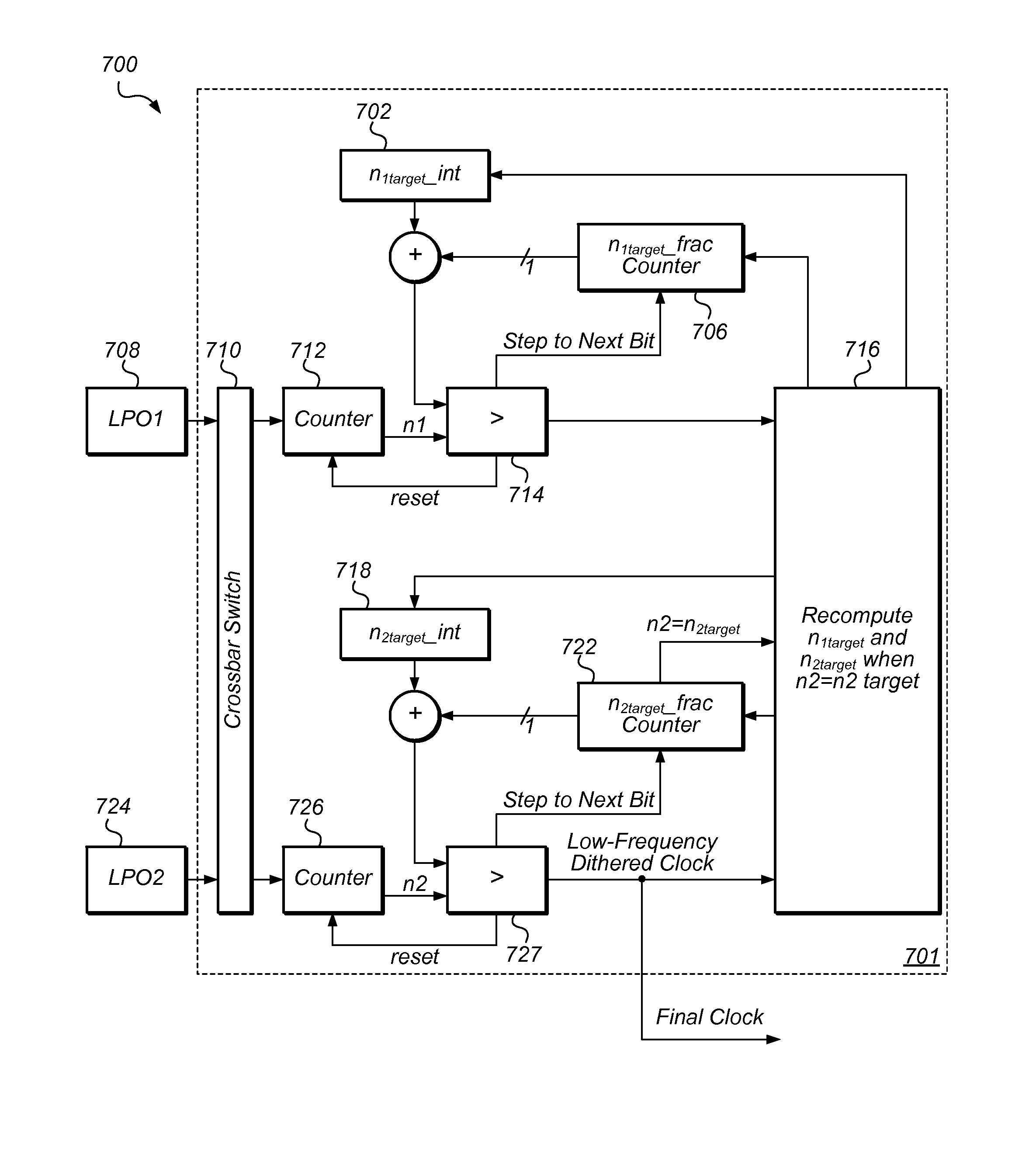
[0009]A single oscillator system may include many different components that do not necessarily correlate with each other. For example, logic and comparator delay, and delays due to RC may not correlate with each other. By using two oscillators, the error contribution by most of the parameters that change with respect to temperature may be eliminated, leaving only the temperature sensitivity of the resistors as a contributing factor. The temperature coefficient of the entire LPO (low-power oscillator) circuit may therefore become more predictable, and more controllable. The output of one LPO may be used as the desired oscillator CLK output, while the output of the other LPO may be used to accurately correct that output as it is changing with temperature.
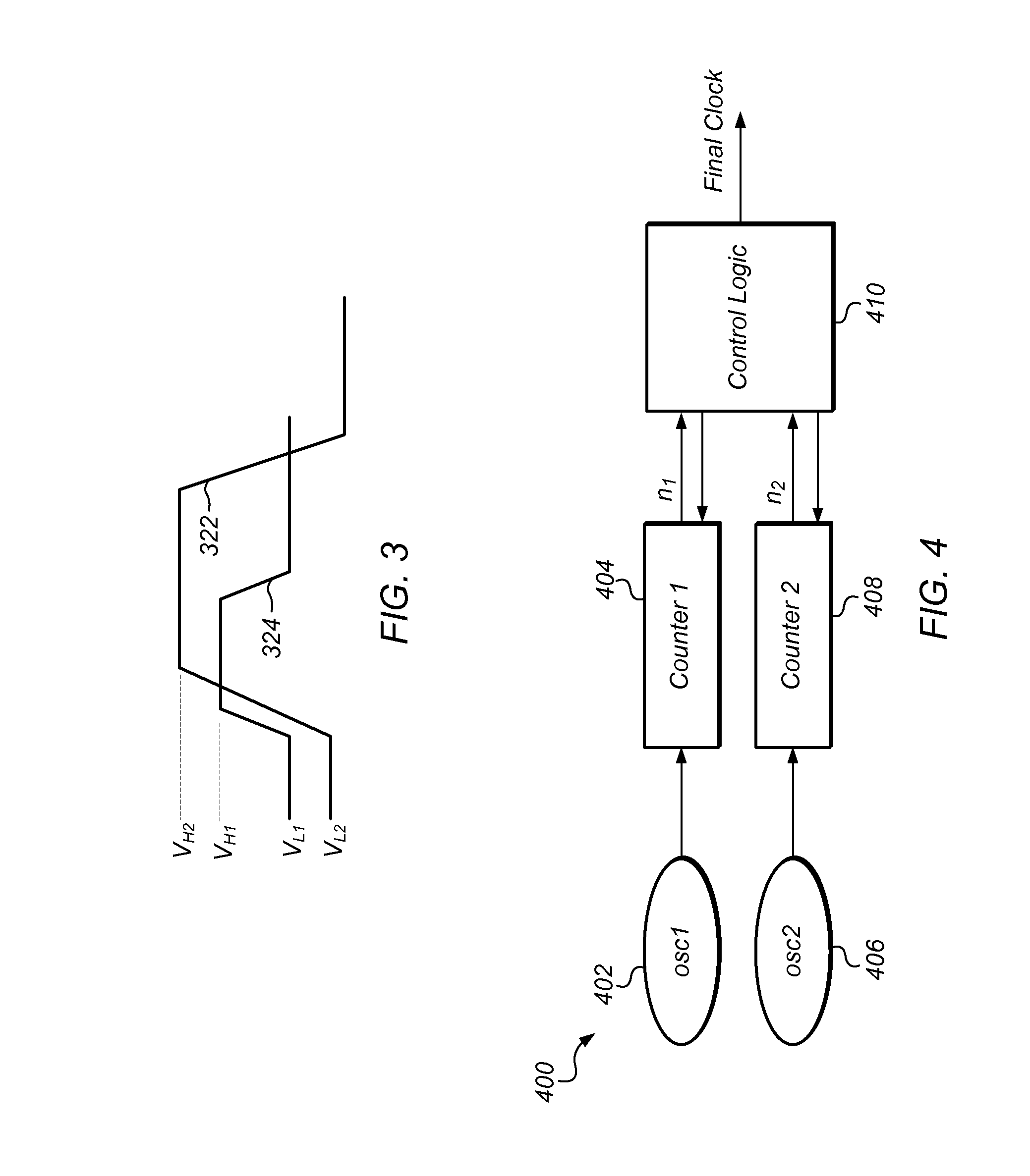
[0011]Power consumption may be reduced such that the two oscillators consume less power together than a single oscillator optimized through prior art methods. Benefits also include relaxed requirements for certain circuit elements. The different output periods may be obtained by moving the threshold on the reference input to the comparator configured in the LPO, as opposed to having different input capacitor and feedback resistor values for the two oscillators. In other words, the value of the feedback resistor (to the oscillator input) may be the same for both oscillators, and the value of the input capacitor may be the same for both oscillators, while the two oscillators have different oscillation periods (frequencies). This may result in the comparators triggering differently, and the difference in period between the two LPO output signals may be obtained by changing the effective value of the reference node of the comparator, thereby causing the two comparators to flip at different times with respect to each other.

Problems solved by technology

Typically, this can be achieved using an external 32 KHz sleep clock, but this adds expense if the crystal doesn't already exist in the system, or if it's hard to route the clock to the device.
In standard CMOS, without a crystal, it is generally difficult to achieve the 250 ppm goal with a single oscillator.
The behavior of such on-chip oscillators is typically affected by the technology used to fabricate the integrated circuit, temperature changes, and supply voltage changes.

Method used


Image

  • Dual self-calibrating low-power oscillator system and operation
  • Dual self-calibrating low-power oscillator system and operation
  • Dual self-calibrating low-power oscillator system and operation

Examples


Embodiment Construction

[0022]In various embodiments, two low-frequency / low-power oscillators configured in a two-oscillator system may be used for tracking time, for example during sleep mode of a system or an integrated circuit (chip). The two-oscillator system may be operated during normal mode to indicate to the chip when to wake up, and may also be operated to provide timing in case the chip wakes up due to an external interrupt. In some embodiments, the two-oscillator system may also provide a clock—of possibly different frequency than the frequency during normal operation—during sleep mode. The maximum allowed frequency drift of the oscillators over time may be determined by the maximum allowed time-error during the wake up time.

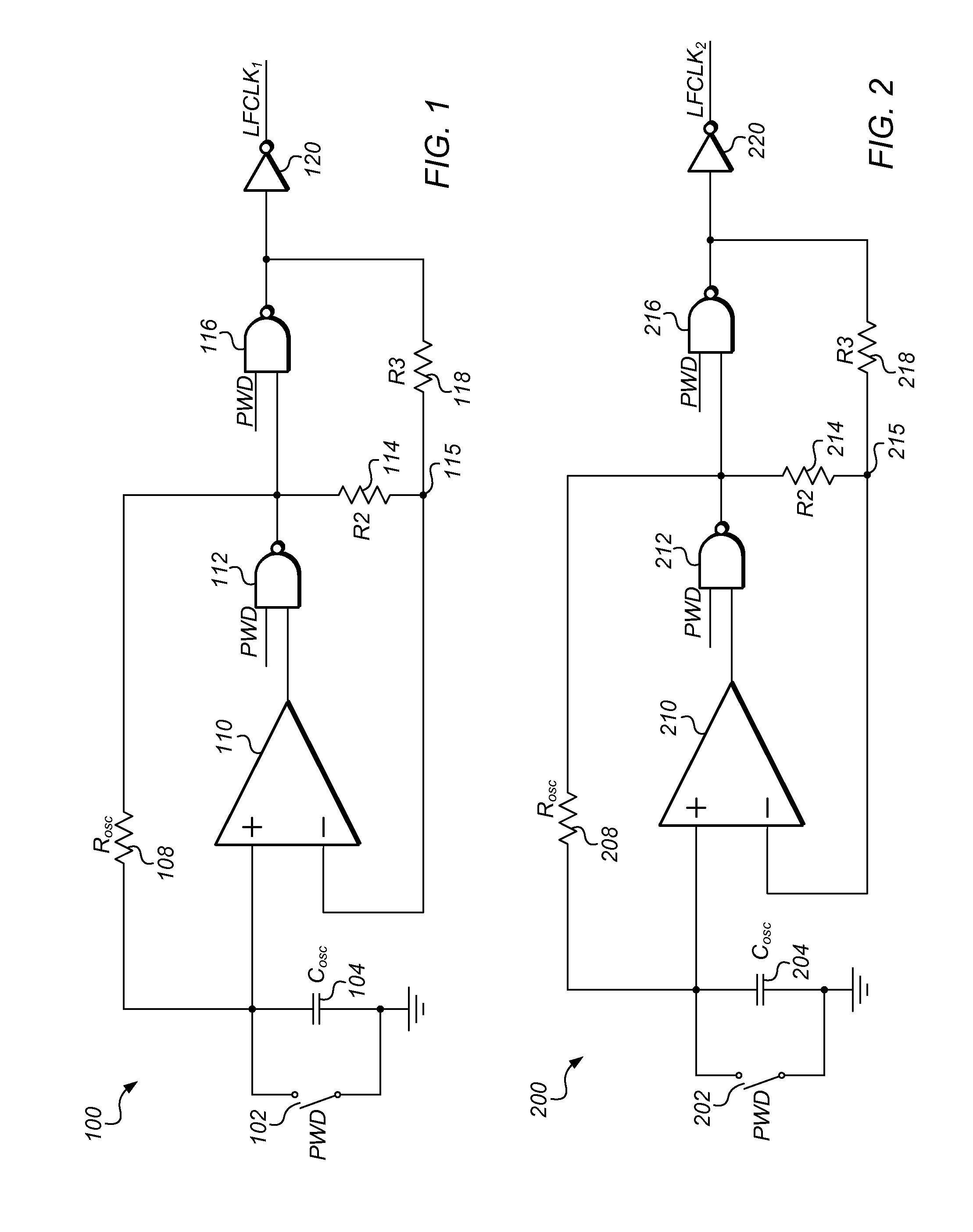
[0023]One possible design of a low power oscillator (LPO) 100 is shown in FIG. 1. LPO 100 may be manufactured using a specified process technology, which may be a 0.13 μm technology process in one set of embodiments. In another set of embodiments, LPO 100 may be manufactured...


PUM


Abstract

A system may include a first circuit configured to generate a first clock having a first period of oscillation, and a second circuit configured to generate a second clock having a second period of oscillation, where the difference (ΔT) between the first period of oscillation and the second period of oscillation remains within a specified limit even during variations in temperature and / or during variations in the supply voltage. The system may further include a control circuit, which may receive the first clock and the second clock, and adjust, according to ΔT, a first target parameter corresponding to a first number of cycles of the first clock, when a current cycle count of the second clock reaches a second target parameter corresponding to a second number of cycles of the second clock. The control circuit may also adjust, according to ΔT, the second target parameter when the current cycle count of the second clock reaches the second target parameter, and generate, based on counted cycles of the second clock, an output clock having an output period higher than the first period and the second period.

Description

BACKGROUND OF THE INVENTION[0001]1. Field of the Invention[0002]This invention relates to oscillator design, and, more particularly, to the design of more accurate low-power oscillators.[0003]2. Description of the Related Art[0004]Wireless protocols like Bluetooth and WLAN (wireless local area network) make provisions for the devices to be placed in sleep mode, but such devices must typically maintain a clock with some amount of accuracy, for example 250 ppm (parts per million) for Bluetooth. Typically, this can be achieved using an external 32 KHz sleep clock, but this adds expense if the crystal doesn't already exist in the system, or if it's hard to route the clock to the device. An internal low power oscillator (LPO) may be designed on-chip, but the oscillation frequency of the LPOs may change as voltage and temperature drift. With careful design, this change may only be a few percent across the entire temperature range, but in terms of ppm 1% may equal 10,000 ppm. In standard C...

Claims


Application Information

Patent Timeline
Patent Type & Authority Patents(United States)
IPC IPC(8): H03L1/00H03L1/02
CPCH03L1/00H03L1/02
Inventor HUSTED, PAUL J.LUTHRA, MANEVCHEN, WEN-HSING
Owner QUALCOMM INC
Learn More