Method and system for acoustic shock detection and application of said method in hearing devices

a technology for detecting acoustic shock and audio signals, applied in the direction of hearing aid testing/monitoring, electrical equipment, etc., can solve the problems of serious sound quality distortion, too slow to be effective, and inability to detect acoustic shock events, etc., to achieve reliable and fast detection of acoustic shock events in audio signals

Active Publication Date: 2011-07-19
SONOVA AG
View PDF7 Cites 10 Cited by
  • Summary
  • Abstract
  • Description
  • Claims
  • Application Information

AI Technical Summary

Benefits of technology

[0016]It is an object of the present invention to provide a method of reliably and fast detecting acoustic shock events in audio signals.
[0017]It is a further object of the present invention to provide an additional method of managing acoustic shock events after its detection in order to input such events to the user in a reasonable range without causing hearing damage or discomfort.
[0018]It is a further object of the present invention to provide a method of detecting reliably and rapidly acoustic shock within an acoustic input signal with a minimum of computational effort and to consequently attenuate or cancel the shock while maintaining the input signal unaffected.
[0030]Thus, the present method provides a quick and reliable shock detector that operates in the time-domain. The shock detection takes place with zero time delay, or even predicts the shock before it fully goes through the signal processing.
[0032]In one embodiment, the method further comprises the step of applying anti-shock gain reduction (g(t)) when a shock event has been indicated. Thus, the acoustic shock is not only detected but as well adaptively reduced, thereby keeping the natural sound quality of the shock events for environmental awareness.
[0035]Thus, there is provided a hearing device with adaptive shock management qualities to achieve a natural anti-shock treatment without impacting audio signals such as speech or music, thus keeping the acoustic shock event natural and comfortable for the user of the hearing device.

Problems solved by technology

Detection of acoustic shock is a well-known problem in signal processing.
MPO (Maximum Power Output) in the frequency domain can be applied to prevent overshooting, but it is also too slow to be effective.
Peak-clipping in the time-domain such as time-domain MPO is effective and fast, but it usually causes serious distortion of sound quality.
However, many fast shocks can be much shorter than 0.5 ms and they may not be detected with this block level.
The additional time-delay is required for the system, but can cause new problems for hearing aid devices since the overall signal delay over 10 ms can be perceived as noticeable acoustic latency, which is not desired.
The shock detection in the sub-band is very expensive cycle budget-wise and also difficult to synchronize with the time-domain parameter extraction.
The sub-band strategy will not be able to detect very fast shocks reliably and accurately since the filter bank can smear the actual sound level change.
It is also not desired to eliminate the shock in individual sub-bands, because this may cause the user to lose environmental awareness and, hence, not perceive correctly the nature of the shock, which might be very important information for the user.
It is also expensive to implement this approach and to optimize this algorithm with existing hearing device technology.
More complex hearing device systems may also suffer from excessive input-output latency or require very expensive computing power to process this strategy.
The signal processing required for the system, particularly peak estimator (prefer to up-sample the input signal), is higher than it is available in low-power digital systems such as digital hearing devices, thus this system is not suitable for miniaturized, low-power digital devices.
On the other hand, the transient signal below 80 dB in the quiet acoustic environment, such as 40 dB, can result in big perceived shock since the gain at this soft input level is usually very high.
Many of these are based on peak-clipping in order to minimize delay, but, which, as previously stated, usually introduce artifacts or distortion into the signal.
However, the problems of distortion or uncomfortable artificial effects still cannot be avoided with adaptive peak clipping.
Although many of these algorithms are quite successful for telecommunication applications, typically experienced by a user through headphones or a headset, they usually need to add more delay and require intensive computational power.
Since hearing devices possess limited computational power, this restricts the application of such techniques.
Furthermore, the requirement in this regard is different in hearing devices compared to other audio devices, in that acoustic shock should never be cancelled out completely in hearing devices, even if technically possible to do so.

Method used


Image

  • Method and system for acoustic shock detection and application of said method in hearing devices
  • Method and system for acoustic shock detection and application of said method in hearing devices
  • Method and system for acoustic shock detection and application of said method in hearing devices

Examples


first embodiment

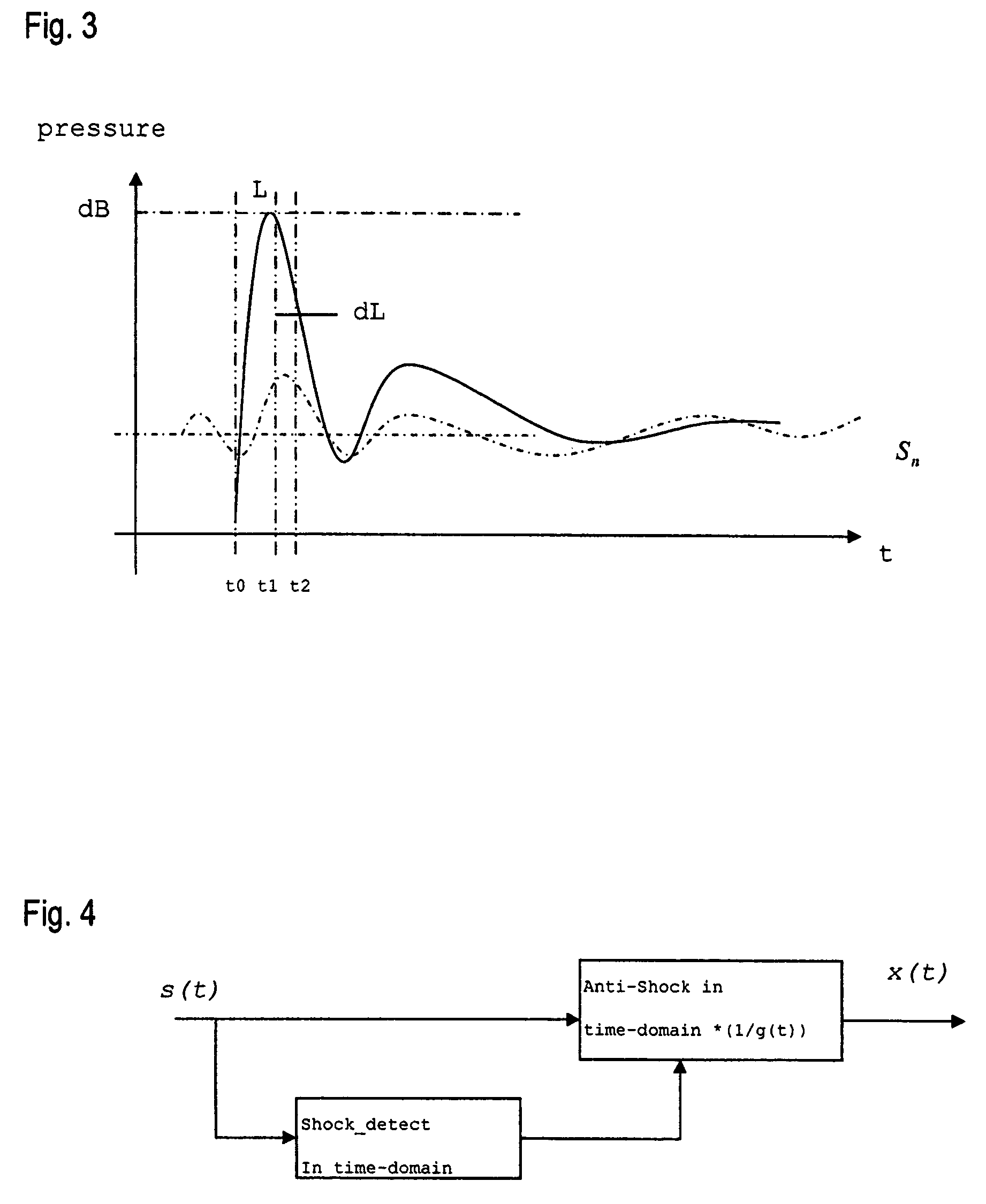
[0072]In a first embodiment, the shock detection and the anti-shock management will be both performed in the time-domain, as depicted schematically in the block diagram of FIG. 4.

[0073]The shock peak thus can be detected without delay but the anti-shock process could be delayed until a shock is detected. Therefore, a few samples of signal delay such as 250 μs (i.e. n=4 for sampling rate 16 kHz) for anti-shock management is required. As can be see from the lower curve of FIG. 5, the whole shock part cannot be handled with the anti-shock process in the time-domain without adding additional delay, which will cause distortion of shock event.

[0074]Hence, additional time delay is required to be added by these few samples in addition to the existing system time delay. Adding additional time delay at this juncture could cause artificial effects on the input signals. The threshold delay beyond which this negative impact would happen is determined by the overall system delay, the type of shoc...

second embodiment

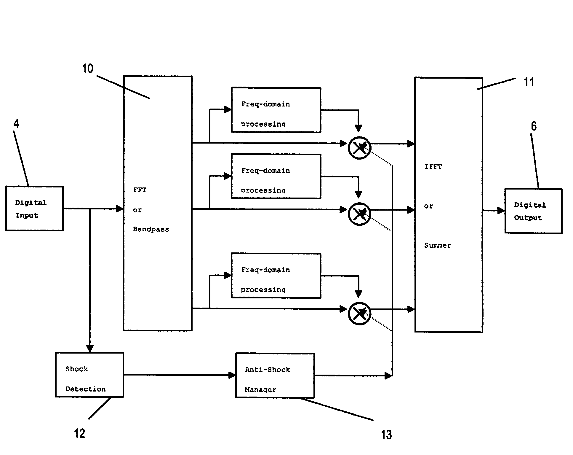
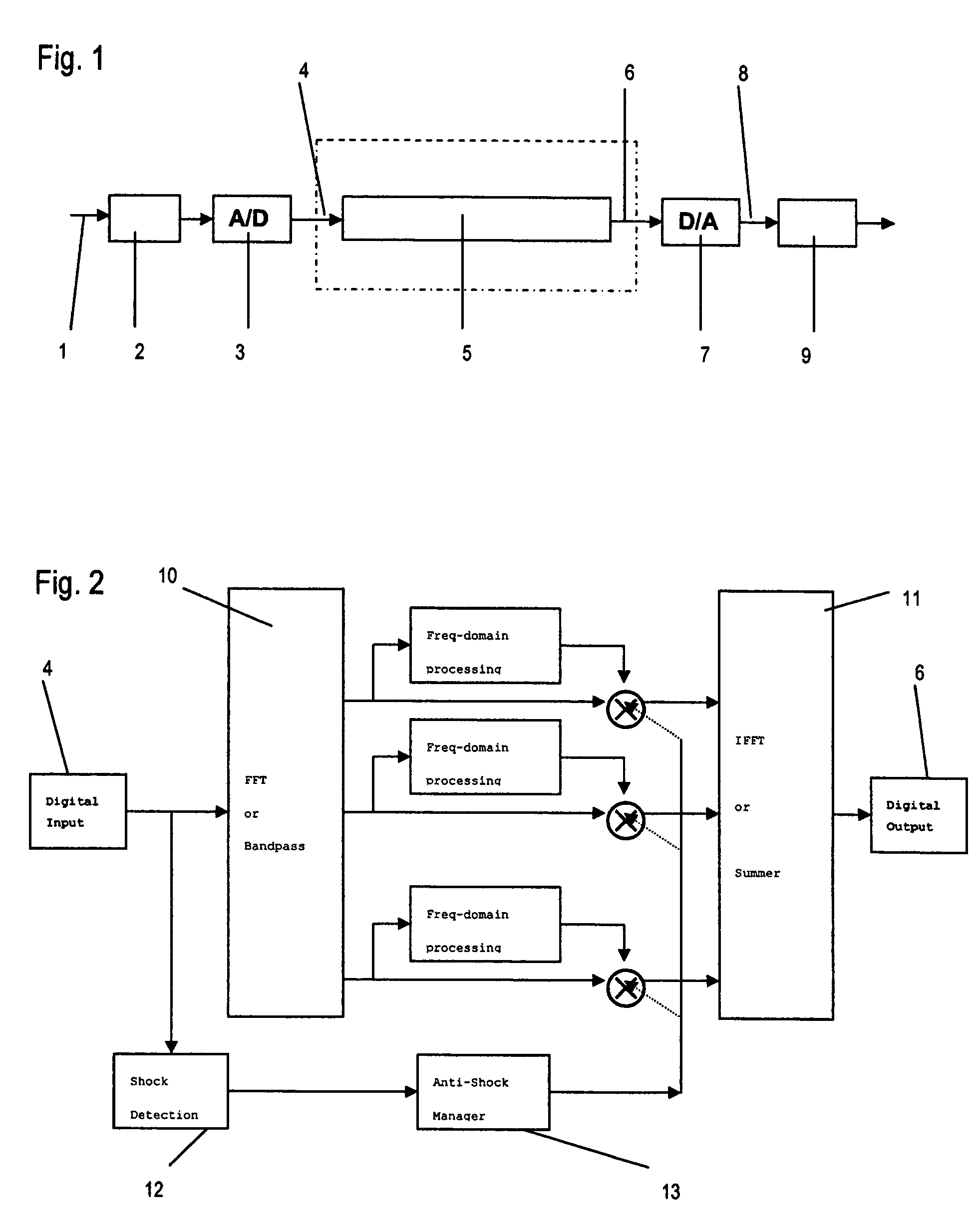
[0083]In the present invention, the shock detection takes place in the time-domain whereas the treatment or management respectively of the signal takes place in the frequency-domain, as depicted schematically in FIG. 6.

[0084]The shock detection will be carried out by the shock detection module 12 in the time domain as already described above with no additional time delay required. The signal s(t) in the time-domain is then transformed into frequency domain by a FFT module 14 for any frequency-domain signal processing in module 15 and the anti-shock management by the anti-shock management module 13. Afterwards, the frequency-domain signal gain (f) is transformed back to time-domain by the FTT module 16 resulting in a new signal y(t).

[0085]For example, the signal transformation from time-domain to frequency-domain and then back to time-domain is frame-based by applying a certain window such as Hanning or Hamming. The frame size is typical 2N samples such as 64 (N=5) for 32-bit FFT, wh...


PUM


Abstract

The present invention provides a method for detecting acoustic shock in an audio input signal (s(t)), comprising the steps of monitoring the input signal (s(t)) in the time-domain. Thereby detecting the signal floor (Sn), detecting the peak level of the input signal (L), detecting the attack time of the input signal (t1-t0), detecting the duration of the input signal (T). Based on those detections, determining a shock contrast level (SCL) as difference between the peak level (L) and the signal floor (Sn), determining a shock index (SI) by use of a shock index normalization constant (σ) and comparing the shock contrast level (SCL) and the shock index (SI) with respective thresholds and indicating an acoustic shock if one or both thresholds are exceeded. Thus, the present method provides a quick and reliable shock detector that operates in the time-domain. The shock detection takes place with zero time delay, or even predicts the shock before it fully goes through the signal processing.

Description

TECHNICAL FIELD[0001]The invention relates generally to a method and system for detecting acoustic shock signals in audio signals and to applications of that method in hearing devices.[0002]Furthermore, the invention relates to further reduce or minimize detected shock effects in audio signals.BACKGROUND OF THE INVENTION[0003]Detection of acoustic shock is a well-known problem in signal processing. Acoustic shock signals are referred to as impulse signals or transient signals. The nature of an impulse signal is such that its amplitude suddenly changes within a very short duration. There are two typical types of transient signals: aperiodic and periodic signals. An aperiodic impulse is for example generated by an explosion, gunfire or a firecracker. Aperiodic shocks last for very short timeframes such as 250 μs or less. On the other hand, a periodic impulse is usually generated from an impact between two mechanically and acoustically un-dampened objects such as two glass bottles hitt...

Claims


Application Information

Patent Timeline
Patent Type & Authority Patents(United States)
IPC IPC(8): H04R29/00
CPCH04R25/30
Inventor LUO, HENRY
Owner SONOVA AG
Why Eureka
Try Eureka