
Fuel cell system and reformer

a fuel cell and reformer technology, applied in the direction of electrochemical generators, chemical/physical processes, chemistry apparatus and processes, etc., can solve the problem of additional temperature variation in the reformer, and achieve the effect of preventing backfir

Inactive Publication Date: 2011-07-26
SAMSUNG SDI CO LTD
View PDF16 Cites 13 Cited by
  • Summary
  • Abstract
  • Description
  • Claims
  • Application Information

AI Technical Summary

Benefits of technology

[0011]Some embodiments provide a fuel cell system, and a reformer for the same, having advantages of supplying fuel to an oxidation catalyst uniformly and preventing backfire.
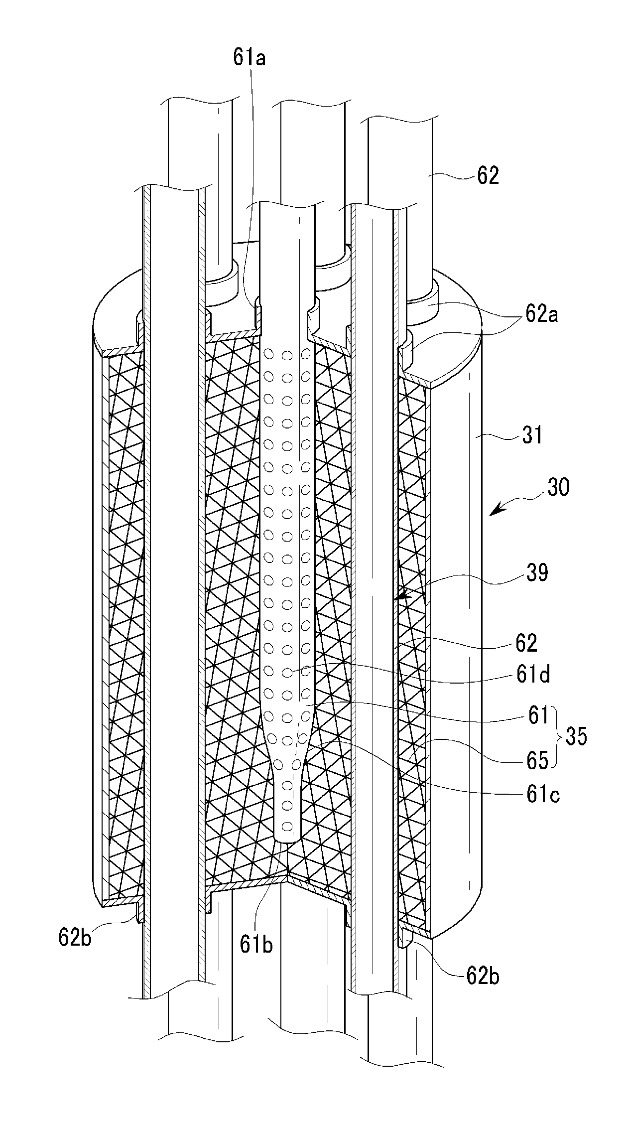
[0012]Some embodiments provide a fuel reformer and a fuel cell system comprising the same. The reformer converts a fuel comprising a hydrocarbon or hydrocarbon group, for example, methanol, ethanol, methane, propane, and the like, into hydrogen gas, which is used by the fuel cell. Embodiments of the reformer exhibit reduced backfire and greater temperature uniformity therein. The reformer comprises a case, a heat source, and a reforming reaction part. In some embodiments, the case is generally cylindrical. The heat source comprises a mesh disposed in the case, an oxidation catalyst disposed on the mesh, and at least one fuel injection nozzle. The fuel injection nozzle comprises a tube with a first open end disposed within the case and a second end, through which fuel is supplied, disposed outside of the case. In some embodiments, the fuel injection nozzle is generally parallel with a longitudinal axis of the case. In some embodiments, an inner diameter of the first end of the fuel injection nozzle is smaller than an inner diameter of the second end of the fuel injection nozzle. Some embodiments of the fuel injection nozzle further comprise a plurality of nozzle holes on a surface thereof. At least one reforming tube extends through the case of the reformer. In some embodiments a plurality reforming tubes are generally symmetrically arranged around a central fuel injection nozzle.
[0019]According to an exemplary embodiment, a catalyst portion includes the mesh and the oxidation catalyst layer formed on the mesh, and thus the fuel can be uniformly supplied to the oxidation catalyst layer. Accordingly, a temperature distribution can be uniform in the entire reformer. Therefore, performance and heat efficiency of the reformer can be improved.
[0020]In addition, the fuel injection nozzle includes a portion in which an internal diameter gradually decreases toward the first end, and a filler disposed in the first end of the open end. Thus, backfire of the fuel injection nozzle can be reduced or prevented.
[0021]Further, according to the exemplary embodiment, the heat source and the reforming reaction part are disposed in the same space. Thus, the size of the reformer can be reduced, and heat efficiency can be improved. Accordingly, the performance of the reformer can be enhanced.

Problems solved by technology

In addition, in a typical reformer, backfire may occur at an end of a fuel injection nozzle, thereby causing additional temperature variation in the reformer.

Method used


Image

  • Fuel cell system and reformer
  • Fuel cell system and reformer
  • Fuel cell system and reformer

Examples


Embodiment Construction

[0035]Hereinafter, certain embodiments will be described more fully hereinafter with reference to the accompanying drawings, in which exemplary embodiments are shown. As those skilled in the art would realize, the described embodiments may be modified in various different ways, all without departing from the spirit or scope of the present disclosure.

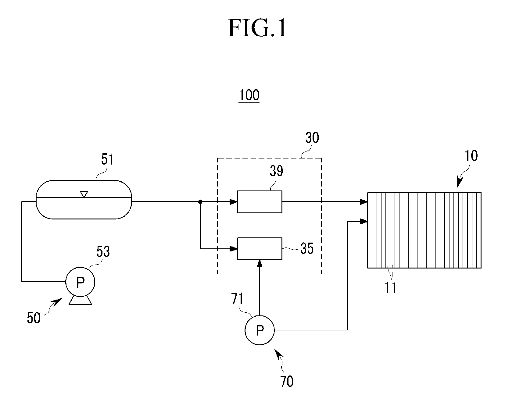
[0036]FIG. 1 is a schematic block diagram of a fuel cell system 100 according to an exemplary embodiment.

[0037]Referring to FIG. 1, a fuel cell system 100 employs a polymer electrolyte membrane fuel cell (PEMFC). Thus, in the fuel cell system 100, hydrogen is generated by reforming a fuel, and electrical energy is generated by electrochemically reacting the hydrogen with oxygen.

[0038]The fuel cell system 100 may use a liquid or gas fuel comprising hydrogen, such as methanol, ethanol, and natural gas. Hereinafter, the fuel cell system 100 using a liquid fuel such as methanol will be described as an example.

[0039]In the fuel cell system 10...


PUM

PropertyMeasurementUnit
heat energyaaaaaaaaaa
internal diameteraaaaaaaaaa
electrical energyaaaaaaaaaa

Abstract

A fuel cell system and a reformer for a fuel cell system prevents backfire and improves efficiency of heat transfer. The fuel cell system includes a reformer generating hydrogen gas from fuel including hydrogen by a catalytic chemical reaction using heat energy, and at least one electricity generating unit generating electrical energy by an electrochemical reaction between the hydrogen gas and oxygen. The reformer includes a case, a heat source, and a reforming reaction part. The case forms an external shape. The heat source is disposed in the case to generate heat energy by an oxidation reaction between fuel and a catalyst, and includes a mesh, an oxidation catalyst layer formed on a surface of the mesh, and at least one fuel injection nozzle supplying the fuel to the oxidation catalyst layer. The reforming reaction part is disposed in the case to generate hydrogen gas from fuel using the heat energy generated from the heat source.

Description

CROSS-REFERENCE TO RELATED APPLICATION[0001]This application claims priority to and the benefit of Korean Patent Application No. 10-2007-0139023, filed in the Korean Intellectual Property Office on Dec. 27, 2007, the entire content of which is incorporated herein by reference.BACKGROUND OF THE INVENTION[0002]1. Technical Field[0003]The present disclosure relates to a fuel cell system and a reformer for a fuel cell system. More particularly, the present invention relates to a fuel cell system and a reformer for a fuel cell system having an improved structure for supplying fuel and an oxidation gas.[0004]2. Description of the Related Art[0005]Fuel cells are an electricity generating system that generate electrical energy through a chemical reaction between hydrogen, which may be part of a hydrocarbon group fuel such as methanol, ethanol, and natural gas, and an oxidation gas supplied separately from the hydrogen.[0006]Polymer electrolyte membrane fuel cell (PEMFC) typically exhibit su...

Claims


Application Information

Patent Timeline
Patent Type & Authority Patents(United States)
IPC IPC(8): H01M8/18
CPCB01J4/002B01J8/062B01J8/065B01J8/067C01B3/323C01B3/384H01M8/0618B01J2208/00309B01J2208/00504B01J2219/00265C01B2203/0227C01B2203/066C01B2203/0811C01B2203/1223C01B2203/1229C01B2203/1241C01B2203/1247Y02E60/50H01M8/04H01M8/06
Inventor LEE, SUNG-CHULKIM, JU-YONGSHIN, WOO-CHEOLLEE, YONG-KULKONG, SANG-JUNSON, IN-HYUKAHN, JIN-GOOKIM, TAE-KEUN
Owner SAMSUNG SDI CO LTD
Learn More