
Optical fiber connector and endoscope system using the same

a technology of optical fiber connector and endoscope, which is applied in the direction of instruments, telescopes, bundled fibre light guides, etc., can solve the problems of increasing the loss of light transmitted through the optical fiber, the tip of the connector is tending to be dusty, and the damage to the end face of the light guide provided, so as to increase the yield rate and cost, and reduce the loss of connection between the first and second graded index fibers

Inactive Publication Date: 2011-07-26
FUJIFILM CORP
View PDF4 Cites 19 Cited by
  • Summary
  • Abstract
  • Description
  • Claims
  • Application Information

AI Technical Summary

Benefits of technology

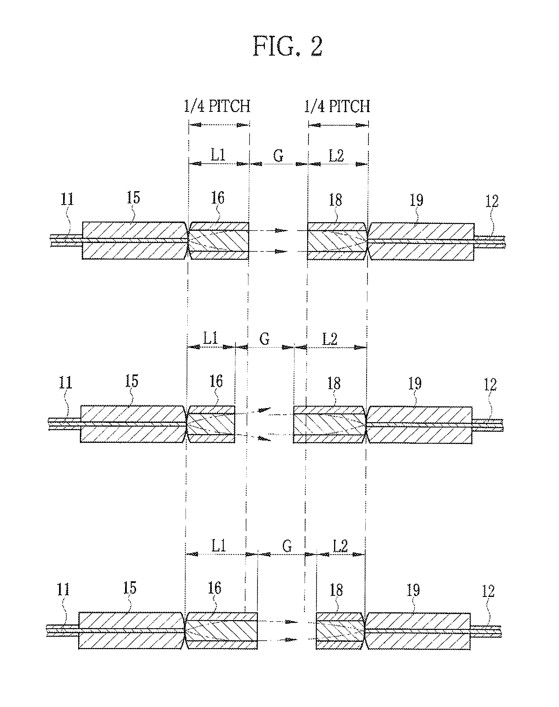
The present invention relates to an optical fiber connector that increases the yield rate of a graded-index fiber used as a collimator lens and provides stable collimation properties. The connector includes a first graded-index fiber detachably attached to a light exit end of a first optical fiber, and a second graded-index fiber detachably attached to a light entry end of a second optical fiber. The graded-index fibers have different lengths from each other and meet a predetermined gap to align their cores. The optical fiber connector may further include anti-reflection films and a connection sleeve for improved optical performance. The invention also includes an optical fiber connector for use in an endoscope system. The combination of graded-index fibers with different lengths from each other composes a collimator lens, resulting in increased yield rate and cost reduction.

Problems solved by technology

Since the connector is often detached from the light source unit, a tip of the connector tends to be dusty.
Besides, the often detachment can cause damage to the end face of the light guide provided in the connector.
If a connection section of the optical fibers becomes dusty or flawed, a connection loss of light transmitted through the optical fibers is increased.
In addition, in a case where the end of the optical fiber has high optical power density, a dust particle or the flaw can catch fire, and the end of the optical fiber and the end of the ferrule can be burnt.
Thus, it is difficult for the multimode fibers to precisely contact end faces of cores with each other by the PC connection.
The dust collection effect occurring in the optical fiber causes increase in the connection loss, as with the dust particle, and can result in the burn of the optical fiber or the fiber fuse phenomenon.
If the break occurs, the ends of the optical fibers require re-polishing with the ferrules, and hence repair becomes a big deal.
Accordingly, the optical fibers are different from those used in the endoscope system in type, a core diameter and the like, and hence the prior arts are not applicable to the optical fibers of the endoscope system.
However, since both ends of the GI fiber is polished before connection to the optical fiber, the GI fiber is difficult to precisely process into a desired length and this causes a low yield rate.
Placing importance on cost, if the GI fibers of various lengths are used, collimation properties become unstable from product to product.
In addition, even if the GI fiber can be processed into the desired length, variations in a refraction index in a longitudinal direction may cause poor collimation properties of the connector.

Method used


Image

  • Optical fiber connector and endoscope system using the same
  • Optical fiber connector and endoscope system using the same
  • Optical fiber connector and endoscope system using the same

Examples


Embodiment Construction

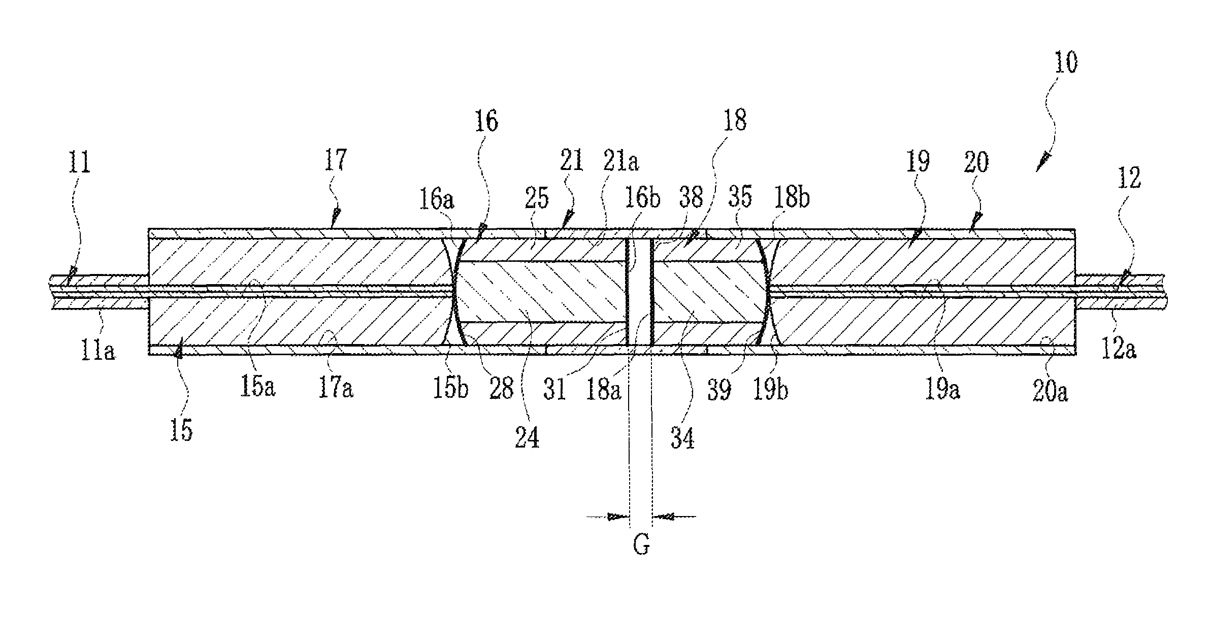
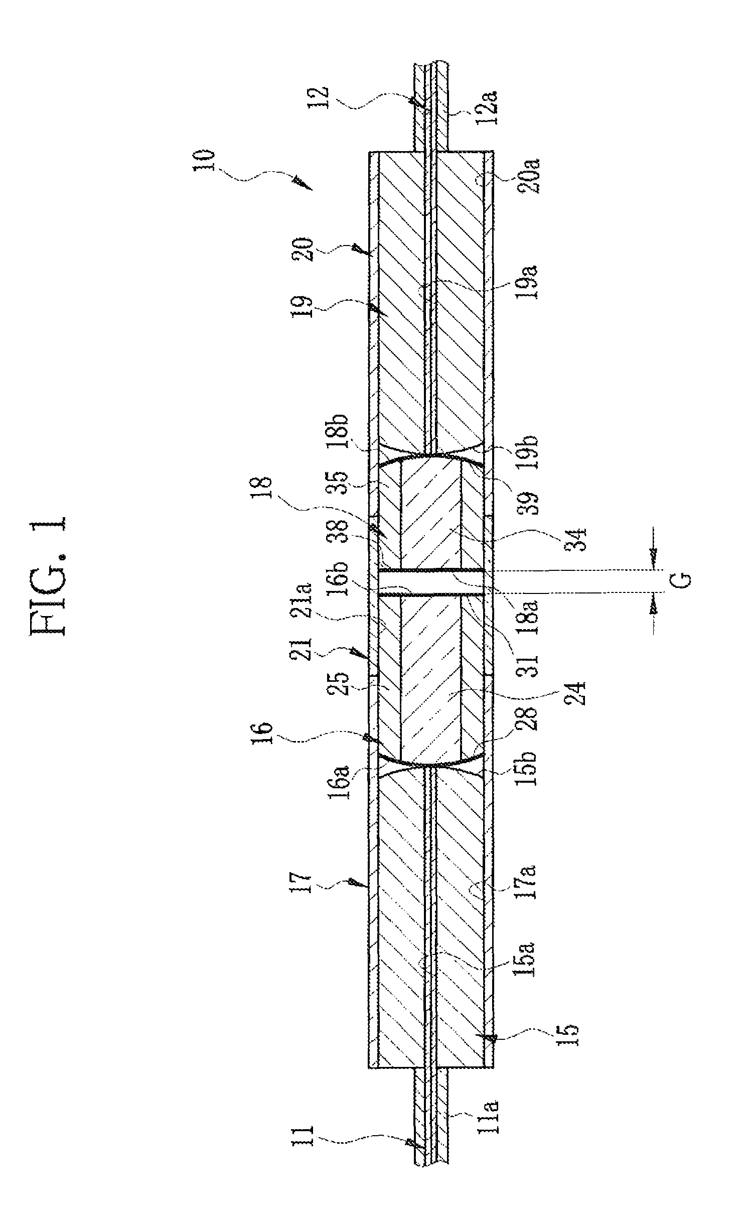
[0035]FIG. 1 shows an optical fiber connector 10 that connects a first optical fiber 11 to a second optical fiber 12. The first and second optical fibers 11 and 12 are multimode fibers that are made of quartz and have a core diameter of 100 μm or more, for example. Laser light having a short wavelength of 405 to 635 nm and a high power of 100 mW or more is transmitted from the first optical fiber 11 to the second optical fiber 12. According to a transmission direction of the laser light, a right side of FIG. 1 is referred to as a front side (distal), and a left side is referred to as a rear side (proximal).

[0036]The optical fiber connector 10 is constituted of a first ferrule 15 for holding a front end portion of the first optical fiber 11, a first fiber stub 16 detachably connected to the first ferrule 15, a first sleeve 17 for holding the first ferrule 15 and the first fiber stub 16, a second ferrule 19 for holding a rear end portion of the second optical fiber 12, a second fiber ...


PUM


Abstract

An optical fiber connector has a first ferrule holding an end of a first optical fiber, a first fiber stub connected to the first ferrule, a second ferrule holding an end of a second optical fiber, and a second fiber stub connected to the second ferrule. The first fiber stub enlarges the beam diameter of light transmitted through the first optical fiber, and produces the collimated light. The second fiber stub reduces the beam diameter of the collimated light, and leads the converging light into the second optical fiber. The first and second fiber stubs are detachably connected inside a connection sleeve across a predetermined gap. First and second GI fibers contained in the first and second fiber stubs satisfy L1≧L2 and L1+L2≅½ pitch, wherein L1 and L2 represent the lengths of the first and second GI fibers, and one pitch is a sinusoidal period of the light transmitted therethrough.

Description

BACKGROUND OF THE INVENTION[0001]1. Field of the Invention[0002]The present invention relates to a detachable optical fiber connector and an endoscope system using this connector, and more specifically relates to the optical fiber connector that is suitable for transmission of high power laser light and the endoscope system using the same.[0003]2. Description Related to the Prior Art[0004]Physical contact connection (hereinafter called PC connection) is known as a method for connecting optical fibers, in which ends of the optical fibers tightly make contact with each other. In the PC connection, an end portion of each optical fiber is inserted into and fixed in a cylindrical ferrule, and an end face of each optical fiber is polished into a convex spherical shape together with an end face of the ferrule. The ferrules with the optical fibers are inserted into both ends of a cylindrical sleeve, so that the polished end faces of the ferrules make contact with each other in the sleeve. T...

Claims


Application Information

Patent Timeline
Patent Type & Authority Patents(United States)
IPC IPC(8): G02B6/32
CPCG02B6/32G02B6/3845G02B6/3846G02B6/3853G02B23/2469
Inventor SHIMOTSU, SHINICHI
Owner FUJIFILM CORP
Learn More