Charge conducting medium

a conducting medium and charge technology, applied in the direction of instruments, coatings, lamination, etc., can solve the problems of reducing glare, presenting a problem to the driver in the rearview mirror, permanently reducing the window's light transmissivity, etc., and achieve the effect of improving the conductivity of the electrochromic layer

Inactive Publication Date: 2011-08-16
UNIV OF WOLLONGONG +1
View PDF2 Cites 102 Cited by
  • Summary
  • Abstract
  • Description
  • Claims
  • Application Information

AI Technical Summary

Benefits of technology

[0029]Preferably the at least one electrochromic layer further comprises a conductive additive which substantially improves the conductivity of the electrochromic layer.
[0052]Preferably the at least one electrochromic layer further comprises a conductive additive which substantially improves the conductivity of the electrochromic layer. Preferably the conductive additive comprises particles of indium tin oxide (ITO).

Problems solved by technology

During night time driving conditions, glare caused by the reflection of following vehicle headlights in these rear-view mirrors presents a problem to the driver.
Often the intensity of light, particularly sunlight, can cause a problem if the light is very bright or the radiation heats the interior or fades materials in the interior of the room or vehicle.
Window glare can be reduced by tinting the windows, however, tinting permanently reduces the window's light transmissivity.
Again, window tinting is unsatisfactory since there is a permanent reduction in transparency where reversibility of transparency would be preferred.
A problem with known electrochromic assemblies that use conventional liquid electrolytes is that the life-time of the assembly is relatively short compared with the life-time of the vehicle mirror or window pane.
Replacement of the electrochromic assembly is costly and inconvenient to the user.
A further problem with known electrochromic assemblies containing liquid electrolytes is that liquid may leak from the assembly and damage the surrounding environment.
This leakage may occur during normal operation or following impact e.g. during an accident.
A further disadvantage of assemblies containing liquid electrolytes is that it is difficult to reduce the profile (or thickness) of the liquid containing assembly since a separator is required to separate the two electrodes so that they do not contact one another.
Usually the separator is a gasket around the border of the assembly, however, it can be difficult to maintain a uniform gap between the electrodes and external or internal stresses can vary the gap between the electrodes resulting in non-uniform performance due to disruption of electric fields.
This is evident in LCD displays where pressure applied externally results in discolouration of the display over a large area.
This becomes especially difficult when trying to construct electrochromic assemblies which are physically large, curved within either a single plane or across two planes.
This additional complexity adds to cost and manufacturability.
Another problem with known electrochromic assemblies is that the materials from which they are constructed are often hazardous to health and the environment.
For example viologens are popularly used as electrochromics however viologens are toxic in contact with skin and if swallowed.
Viologens also irritate the respiratory system and the skin and are toxic to aquatic organisms and may cause long-term adverse effects in the aquatic environment.
A disadvantage of solid electrolytes is that the electrochromic layer and the solid electrolyte usually have rigid structures which must continuously expand and contract to allow ions to enter and leave the electrochromic layer.
Ultimately mechanical strains develop at the interface of the electrochromic layer and the solid electrolyte resulting in overall degradation of the electrochromic assembly.
In particular such assemblies exhibit a hazing or crazing due to light scattered by cracks and the colour or transparency change of the assembly is also diminished due to the resultant impeded ion flow.
Furthermore, known electrochromic assemblies can be difficult and / or costly to assemble during manufacturing which is inconvenient for efficient, cost-effective production.

Method used


Image

  • Charge conducting medium
  • Charge conducting medium
  • Charge conducting medium

Examples


example 1

[0153]In one example of the present invention a glass support (measuring 30 cm×30 cm) with a thin ITO film acting as an electrode and a metallic strip (indium solder) running down one edge, making up the first electrode had poly(3,4-ethylenedioxythiophen) / poly(styrenesulfonate), Aldrich Cat no. 483095 (PEDOT) airbrushed onto it.

[0154]A second glass support (measuring 30 cm×30 cm) with an ITO electrode with another metallic strip (indium solder) running down one edge had Polypyrole (PPY) airbrushed on. The loading of the conducting polymers on the electrodes was determined via transmission measurement of the individual electrodes in a spectrophotometer (Hunterlab Colorquest XE). For PEDOT an optimum loading corresponded to 55% photopic transmission and for PPY an optimum loading corresponded to a photopic transmission of 60%. It has been determined, through Transverse Electron Microscopy that this equates to film thicknesses around 100 nm.

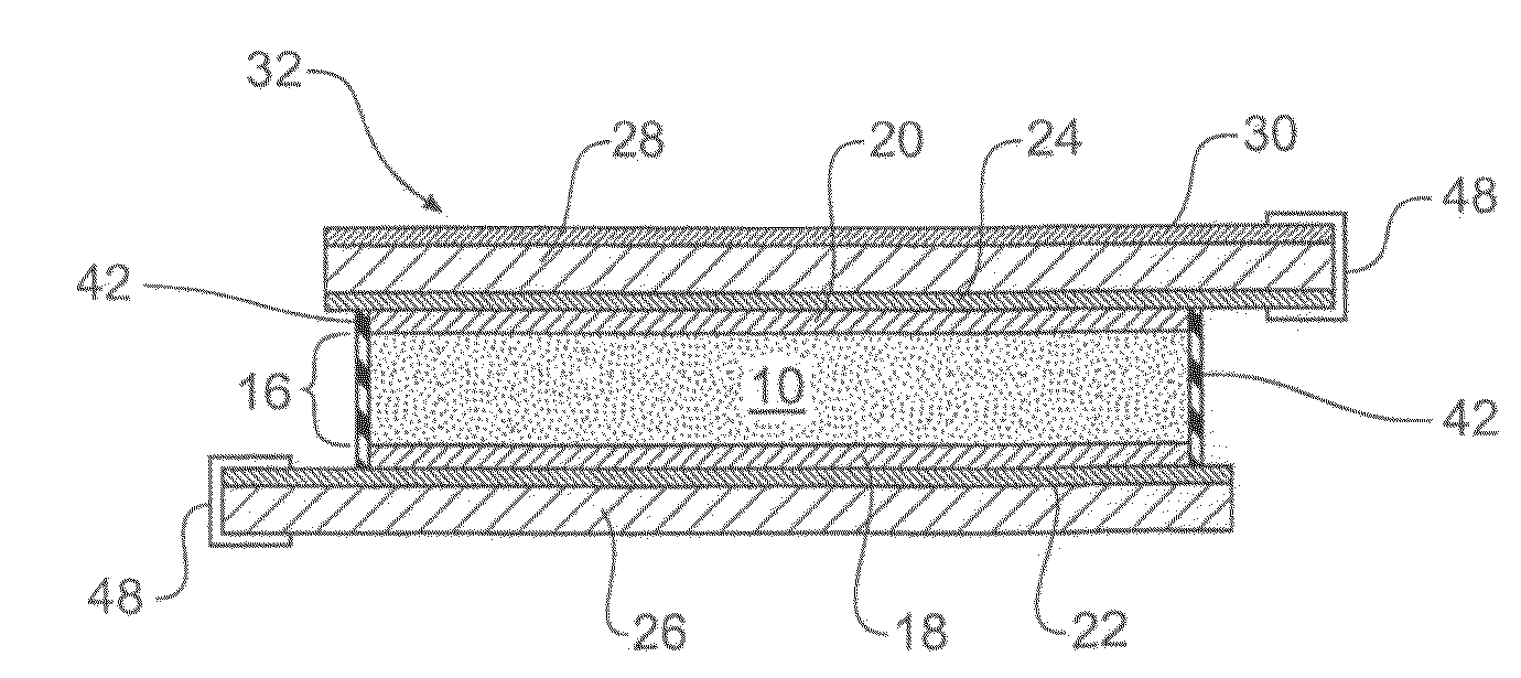
[0155]The electrodes were brought together ar...

example 2

[0159]In another example of the present invention a glass support (measuring 10 cm×10 cm) with an ITO electrode and a metallic strip running down one edge, making up the first electrode had PRODOT deposited on it. A second glass support had Polyanline airbrushed onto it.

[0160]The electrodes were brought together around the PVDF (polyvinylidene difluoride) membrane infused with ionic liquid (1-ethyl-3-methyl imadozolium bistrifluoromethane sulfonimide).

[0161]The assembly was sealed with a two part epoxy resin. A potential of 1.5V was applied to the metallic strips (busbars). A substantial uniform darkening occurred and on reversal of the potential a substantial uniform lightening occurred. The response time for each transition was in the order of 1 second.

example 3

[0162]In another example of the present invention a polyethylene terephthalate support (measuring 7 cm×7 cm) with an ITO electrode and a metallic strip running down one edge had PEDOT airbrushed on. The second support (measuring 7 cm×7 cm) also with a metallic strip had PPY airbrushed onto it.

[0163]The electrodes were brought together around the PVDF (polyvinylidene difluoride) membrane infused with ionic liquid (1-ethyl-3-methyl imadozolium bistrifluoromethane sulfonimide).

[0164]The assembly was sealed with polyurethane glue and a potential of 1.5V was applied to the metallic strips (busbars). A uniform darkening occurred on reversal of the potential a uniform lightening occurred. The assembly was flexed around a diameter of approximately 100 mm and continued to operate.


PUM

PropertyMeasurementUnit
diameteraaaaaaaaaa
diameteraaaaaaaaaa
pore sizeaaaaaaaaaa

Abstract

An electrochromic assembly 32 is disclosed. The assembly comprises: first and second electrodes 22, 24, at least one electrode being transparent; a porous membrane 10 defining a plurality of pores, the membrane having a first refractive index and located between the electrodes 22, 24; an electrolyte filling the pores, the electrolyte having a second refractive index substantially matching the first refractive index, the electrolyte and membrane together forming a substantially transparent electrolytic layer; and at least one electrochromic layer 18 covering at part of the first electrode 22. The membrane 10 is flexible and the spacing between the electrodes 22, 24 is held substantially constant by the membrane 10. The membrane is sealed with sealant 42.

Description

FIELD OF THE INVENTION[0001]The present invention relates to electrochromic assemblies and in particular to electrochromic assemblies that have the capacity to vary the amount of transmitted or reflected light.BACKGROUND[0002]Modern vehicles are equipped with an interior rear-view mirror which, in use, is positioned to allow the driver to view other vehicles behind his or her vehicle. During night time driving conditions, glare caused by the reflection of following vehicle headlights in these rear-view mirrors presents a problem to the driver. There is a need to reduce this glare while allowing the driver to continue to see behind the vehicle.[0003]Known solutions to night time headlight glare have included interior rear-view mirrors that are manually manipulable between a daytime reflecting position and a night-time reflecting position. These mirrors use first and second surface reflections from prisms with a reflective coating on one surface.[0004]Window panes are common in buildi...

Claims


Application Information

Patent Timeline
Patent Type & Authority Patents(United States)
IPC IPC(8): G02F1/153
CPCG02F1/1525G02F1/1533Y10T156/1092G02F2001/1519G02F2001/1515G02F1/15165G02F2001/164
Inventor MAZURKIEWICZ, JAKUB HENRYKWALLACE, GORDON GEORGEINNIS, CHARLES PETEREDWARDS, SCOTT A.MURPHY, PETER J.HALL, COLINFABRETTO, RICK
Owner UNIV OF WOLLONGONG
Why Eureka
Try Eureka