Optical disc apparatus and method for controlling the same

a technology of optical discs and optical discs, applied in the field of optical disc apparatuses, can solve the problems of insufficient noise reduction, inability to solve problems, and degrade the recording layer, and achieve the effect of reducing laser noise and good recording or reproduction operation

Inactive Publication Date: 2011-08-16
HITACHI-LG DATA STORAGE +1
View PDF9 Cites 3 Cited by
  • Summary
  • Abstract
  • Description
  • Claims
  • Application Information

AI Technical Summary

Benefits of technology

[0009]In order to avoid the affect of the quantization noise, it is possible to increase the laser diode emission power and obtain a good S / N (Signal / Noise) ratio. However, if the reproduction operation is performed with the high emission power, the recording layer may be degraded and data may be erased. This is because, the reproduction power is generally lower than the recording power and if the emission power is increased so much, the recording power is achieved during the reproduction operation. For this, firstly, light emission is performed with a good S / N ratio by a high emission power and then the light intensity may be attenuated by the attenuator before the laser beam is applied onto the optical disc recording layer. Thus, it is possible to realize reproduction with a good S / N ratio without degrading the recording layer or erasing data.
[0011]This causes new problems such that the noise cannot be reduced sufficiently or that the laser may emit light with an excessively high power so as to compensate the temperature characteristics of the optical parts, which in turn shortens the laser service life or increases the power consumption.
[0013]It is therefore a first object of the present invention to provide an optical disc apparatus capable of reducing the laser noise and performing good recording and reproduction operation even if the optical parts of the optical pickup have individual irregularities and temperature characteristics, and a method for controlling the apparatus.
[0016]It is therefore a second object of the present invention to provide an optical disc apparatus requiring a time for change of the light attenuation factor but capable of reducing the laser noise and realizing a good recording or reproduction operation and a method for controlling the apparatus.
[0019]According to the present invention, it is possible to provide an optical disc apparatus capable of reducing the laser noise and obtaining a good recording or reproduction operation and a method for controlling the apparatus.

Problems solved by technology

However, if the reproduction operation is performed with the high emission power, the recording layer may be degraded and data may be erased.
However, even if the attenuator is used to obtain a high-density recording, it is impossible to solve the problem that optical parts constituting the optical pickup have individual irregularities and temperature characteristics, which requires a change in the laser diode emission power while maintaining a constant irradiation power onto the optical disc recording layer.
This causes new problems such that the noise cannot be reduced sufficiently or that the laser may emit light with an excessively high power so as to compensate the temperature characteristics of the optical parts, which in turn shortens the laser service life or increases the power consumption.

Method used


Image

  • Optical disc apparatus and method for controlling the same
  • Optical disc apparatus and method for controlling the same
  • Optical disc apparatus and method for controlling the same

Examples


embodiment 1

[0037]Explanation will be given on an example of the optical disc apparatus which changes the light attenuation factor of the attenuator according to the optical system efficiency of the optical pickup according to the embodiment.

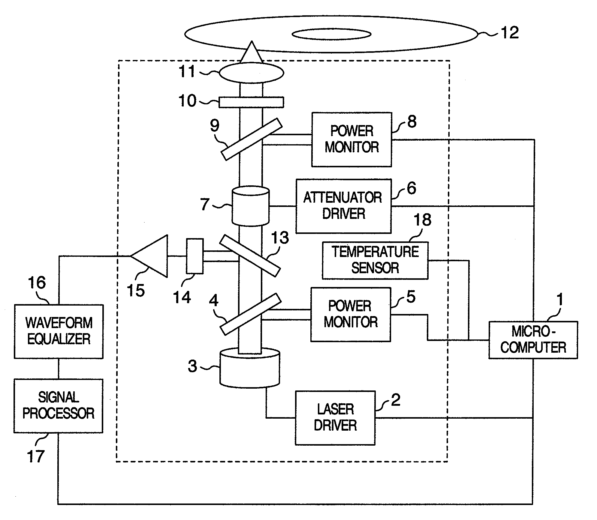
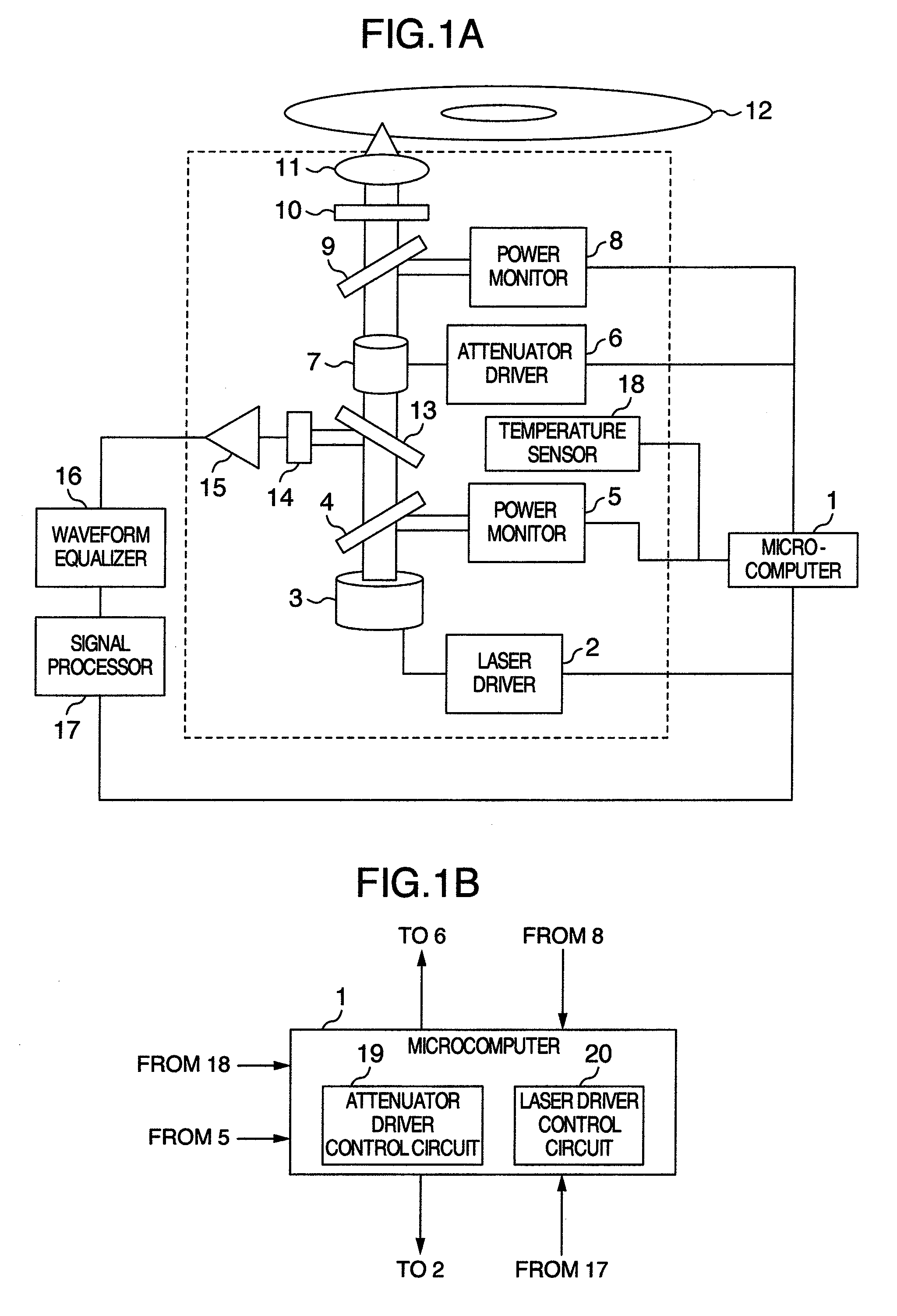
[0038]FIG. 1A is a block diagram showing an optical disc apparatus according to the embodiment of the present invention. A microcomputer 1 performs light emission control such as recording and reproduction onto / from a laser driver 2. The laser driver 2 outputs current to drive a laser diode 3. The laser diode 3 emits a laser beam having a wavelength of, for example, 400 nm with a light emission waveform corresponding to the output of the laser driver 2. A power monitor 5 and a power monitor 8 are detectors which detect information, such as the light intensity. The power monitor 5 detects an emission power of the laser diode 3 via a beam splitter 4, converts the detected power into a voltage value, and outputs it to the microcomputer 1. An attenuator driver ...

embodiment 2

[0084]In this embodiment, explanation will be given on an optical disc apparatus which detects completion of a light attenuation factor change of an attenuator and a method for controlling the apparatus. The block diagram of the optical disc apparatus used in this embodiment is identical to FIGS. 1A, 1B explained in the first embodiment.

[0085]FIG. 7 is an example of a flowchart showing the processes from the moment when the optical disc apparatus starts changing the light attenuation factor of the attenuator to the moment when the reproduction or recording is started. The timing of the light attenuation factor change may be, for example, the disc-loading time, a periodical timing, an arbitrary timing specified by the user like the timings for performing S101, S109, S111, S112 in FIGS. 5A, 5B or the aforementioned (i) to (iii) when the reproduction power is changed. In addition to these, in this embodiment, it is also possible to use the timing when the reproduction operation and the...


PUM

PropertyMeasurementUnit
wavelengthaaaaaaaaaa
transmittanceaaaaaaaaaa

Abstract

An optical disc apparatus capable of obtaining an effect to reduce the laser noise without shortening the laser diode service life or increasing the power consumption. The optical disc apparatus includes a laser diode for emitting a laser beam, a laser driver for driving the laser diode, a detector for monitoring a first power emitted from the laser diode, a detector for monitoring a second power applied to an optical disc, and an attenuator for attenuating the first power. The light attenuation factor of the attenuator is changed by the ratio between the first power and the second power.

Description

INCORPORATION BY REFERENCE[0001]The present application claims priority from Japanese application JP2007-064336 filed on Mar. 14, 2007, the content of which is hereby incorporated by reference into this application.BACKGROUND OF THE INVENTION[0002]The present invention relates to an optical disc apparatus which performs recording or reproduction while reducing a laser noise of a laser diode and a method for controlling the apparatus.[0003]Recently, the digital versatile disc (hereinafter, referred to as DVD) attracts an attention as a high-density optical disc capable of recording large-volume digital information. However, as the information volume increases, the optical disc should have a higher density. Here, in order to achieve a higher density of recording than a DVD, it is necessary to record a mark smaller than the DVD on the recording layer. For this, the light source should have a short wavelength and the objective lens should have a large numerical aperture (hereinafter, re...

Claims


Application Information

Patent Timeline
Patent Type & Authority Patents(United States)
IPC IPC(8): G11B7/00
CPCG11B7/126G11B7/1263
Inventor SHIOZAWA, MANABU
Owner HITACHI-LG DATA STORAGE
Why Eureka
Try Eureka