Power unit having engine and continuously variable transmission, configuration thereof, and vehicle incorporating same

a technology of power units and transmissions, applied in the direction of jet propulsion mounting, gearing, hoisting equipment, etc., can solve the problems of lowering large starters, and the requirement of large-sized, high-capacity starters, so as to enhance the maneuverability of the vehicle at the time of starting the vehicle, reduce the load applied to the starter, and enhance the maneuverability

Inactive Publication Date: 2011-08-23
HONDA MOTOR CO LTD
View PDF75 Cites 21 Cited by
  • Summary
  • Abstract
  • Description
  • Claims
  • Application Information

AI Technical Summary

Benefits of technology

[0029]According to the power unit of the vehicle as described in the first aspect, the transmission input clutch, which allows or interrupts the transmission of the rotational drive force of the crankshaft to the drive pulley, is arranged between the crankshaft and the drive pulley. The starter clutch, which allows or interrupts the transmission of a rotational drive force of the driven pulley shaft to the drive wheel, is arranged between the driven pulley and the drive wheel. The transmission input clutch and the starter clutch are arranged with the CVT sandwiched therebetween in a state that the transmission input clutch is arranged on one of sides which sandwich the belt therebetween and the starter clutch is arranged on another side.
[0030]Therefore, even when the starter clutch is disengaged before the CVT assumes a low speed state at the time of stopping the vehicle, the rotational drive force of the crankshaft is transmitted to the CVT by way of the transmission input clutch. As a result, it is possible to bring the CVT from a high speed state into a low speed state whereby the maneuverability of the vehicle at the time of starting the vehicle can be enhanced.
[0031]Further, it is possible to interrupt the transmission of the rotational drive force of the crankshaft to the drive pulley at the time of starting the engine. Hence, a load applied to the starter can be reduced thus realizing miniaturization of the starter.
[0032]Further, the transmission input clutch and the starter clutch, which are heavy components (objects), can be arranged on both sides in the vehicle-width direction in a well-balanced manner with the CVT sandwiched therebetween. Hence, the maneuverability of the vehicle can be enhanced.
[0033]According to the power unit as described in the second aspect of the present invention, the transmission input clutch is mounted on a shaft portion of the drive pulley shaft, and the starter clutch is mounted on a shaft portion of the driven pulley shaft. Accordingly, the shaft on which the respective pulleys are mounted and the shaft on which the respective clutches are mounted are formed of the same shafts. Hence, compared to a power unit in which shafts are provided separately for the clutches and the pulleys, the number of shafts can be decreased which results in decreased number of parts such that the miniaturization of the power unit including the engine can be realized.
[0034]According to the power unit as described in the third aspect, the power includes the oil pump which supplies oil to the CVT, the transmission input clutch and the starter clutch, and a water pump which circulates cooling water inside the engine. The transmission input clutch, the oil pump and the water pump are arranged with the CVT sandwiched therebetween in a state that the oil pump and the water pump are mounted on the shaft portion of the drive pulley shaft on a side opposite to mounting of the transmission input clutch on the other side of the CVT.

Problems solved by technology

However, there exists a possibility that the CVT is driven in a high speed state at the time of starting the vehicle next time thus lowering the maneuverability of the vehicle.
Further, a large-sized starter is required for starting the engine when the starter clutch is mounted on the shaft portion of the drive pulley shaft because a large load is applied to the starter since the starter drives the CVT while rotating the crankshaft.
Therefore, mounting of the starter clutch on the shaft portion of the drive pulley shaft leads to a requirement of a large-sized, high capacity starter.

Method used


Image

  • Power unit having engine and continuously variable transmission, configuration thereof, and vehicle incorporating same
  • Power unit having engine and continuously variable transmission, configuration thereof, and vehicle incorporating same
  • Power unit having engine and continuously variable transmission, configuration thereof, and vehicle incorporating same

Examples


first embodiment

[0062]First of all, the first embodiment of the power unit including an engine and a continuously variable transmission for a vehicle such as a motorcycle, according to the present invention is discussed below in conjunction with FIG. 1 to FIG. 7.

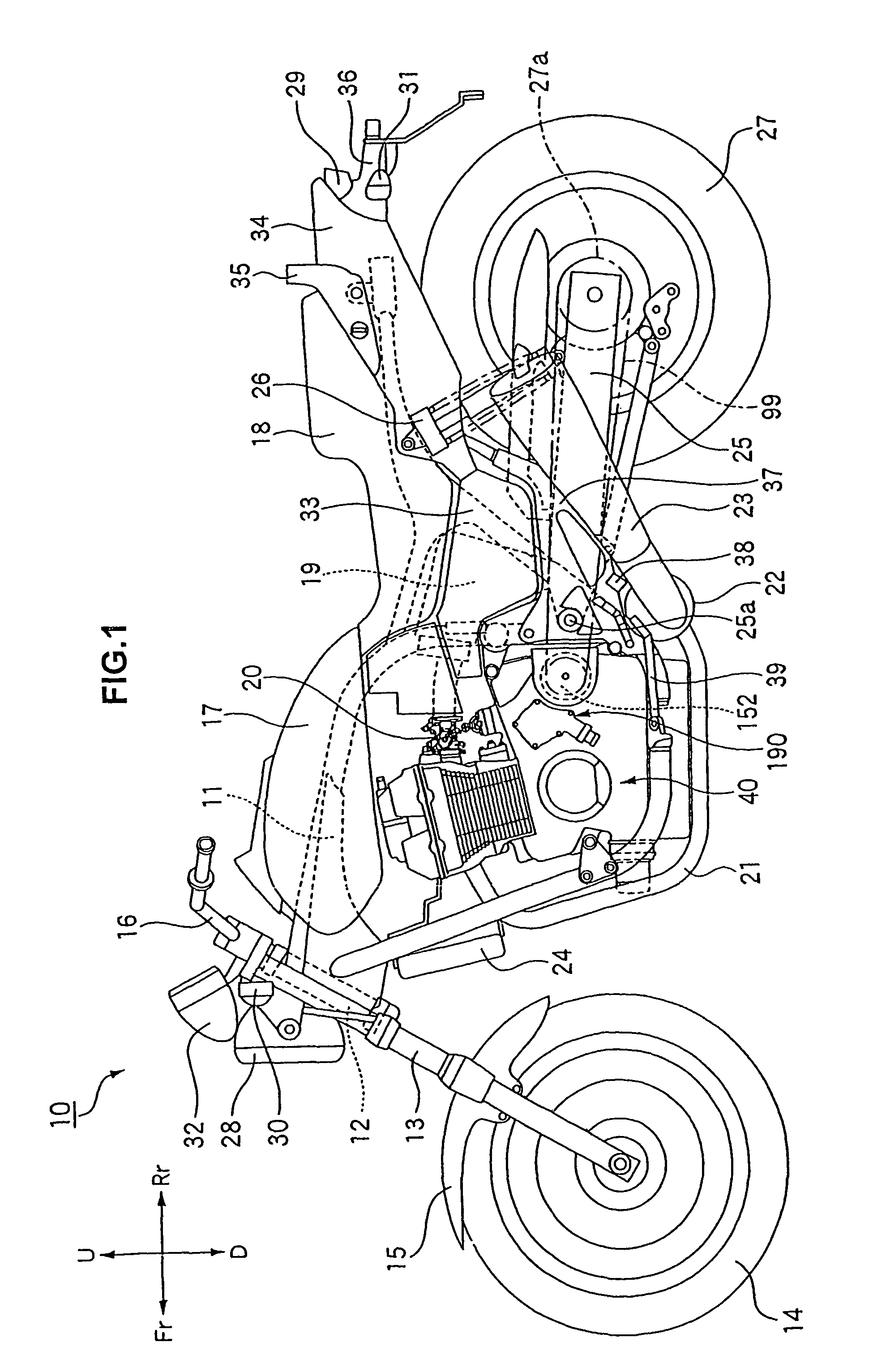
[0063]As shown in FIG. 1, a vehicle (motorcycle) 10 of the present invention includes a cradle type vehicle body frame 11, a front fork 13 which is mounted on a head pipe 12 of the vehicle body frame 11, a front wheel 14 and a front fender 15 which are mounted on the front fork 13, a handle 16 which is connected to the front fork 13, a fuel tank 17 which is mounted on a front upper portion of the vehicle body frame 11 in a striding manner, a seat 18 (a double seat having a rider's seat and a pillion's seat) which is mounted on a rear upper portion of the vehicle body frame 11.

[0064]The motorcycle 10 includes a power unit (having an engine 40 and a continuously variable transmission 100) arranged in the a cradle space surrounded by respectiv...

second embodiment

[0132]Next, the second embodiment of the power unit is discussed in conjunction with FIG. 8. Here, same symbols are given to parts / elements which are identical with or similar to the parts of the first embodiment in the drawing and their explanation is omitted or simplified.

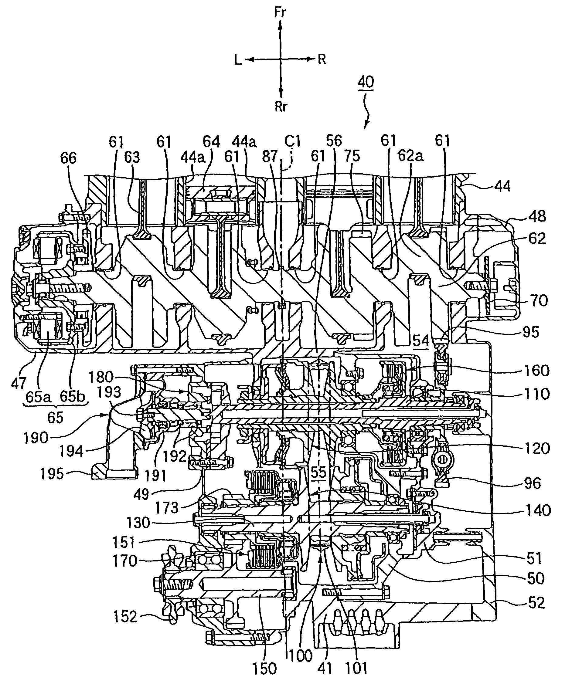
[0133]In the power unit of the second embodiment, a final drive gear 173 mounted on a shaft portion of a driven pulley shaft 130 and is arranged between a driven pulley 140 a starter clutch 170 in the vehicle-width direction. A double row ball bearing 203 which rotatably supports an output shaft 150 is arranged more inwardly of the vehicle-width direction (i.e., towards the center line of the vehicle) than a ball bearing 201 which rotatably supports the driven pulley shaft 130.

[0134]According to the second embodiment, the driven pulley shaft 130 is rotatably supported on the ball bearing 201 and a ball bearing 202 which are mounted on a first transmission case 49 and a second transmission case 50, respectively. T...


PUM


Abstract

A power unit includes an engine having a crankshaft, and a continuously variable transmission having a drive pulley operatively connected with the crankshaft, a driven pulley, and a belt extended between and wrapped around the drive pulley and the driven pulley. The power unit further includes a transmission input clutch, which allows or interrupts the transmission of a rotational drive force of the crankshaft to the drive pulley, mounted on a drive pulley shaft; and a starter clutch, which allows or interrupts the transmission of a rotational drive force of the driven pulley to the drive wheel, mounted on a driven pulley shaft. The transmission input clutch and the starter clutch are arranged such that a continuously variable transmission is sandwiched therebetween.

Description

CROSS-REFERENCE TO RELATED APPLICATIONS[0001]The present application claims priority under 35 USC §119 based on Japanese patent application No. 2006-356242, filed on Dec. 28, 2006. The entire subject matter of this priority document is herein incorporated by reference.BACKGROUND OF THE INVENTION[0002]1. Field of the Invention[0003]The present invention relates to a power unit having an engine and a continuously variable transmission (CVT), and to a vehicle incorporating same. More particularly, the present invention relates to a power unit having a hydraulically-operated CVT and to an arrangement (layout) of various components of the CVT within the power unit.[0004]2. Description of the Backgound Art[0005]There are known power units for a vehicle, such as a motorcycle, having an engine and a CVT. In such power units, a power transmission chamber, which is integrally formed with a crank chamber of the engine, is generally disposed behind the crank chamber of the engine.[0006]The cont...

Claims


Application Information

Patent Timeline
Patent Type & Authority Patents(United States)
IPC IPC(8): F16H55/56B60S9/205B60S9/21B60S9/10B60S9/20B60K17/04F02B61/02F16H57/023F16H57/035F16H57/04
CPCF02B61/02
Inventor SHIOZAKI, TOMOOMITSUBORI, TOSHIMASAHARA, ERIKA
Owner HONDA MOTOR CO LTD
Why Eureka
Try Eureka