Process for the preparation of a sintered ceramic spark plug

a technology of sintered ceramic and spark plugs, which is applied in the field of sintered ceramic spark plug preparation, can solve the problems of limiting the lifetime, shortening the life of the spark plug comprising these materials, and limiting the lifetim

Inactive Publication Date: 2011-08-23
AEVA
View PDF9 Cites 32 Cited by
  • Summary
  • Abstract
  • Description
  • Claims
  • Application Information

AI Technical Summary

Benefits of technology

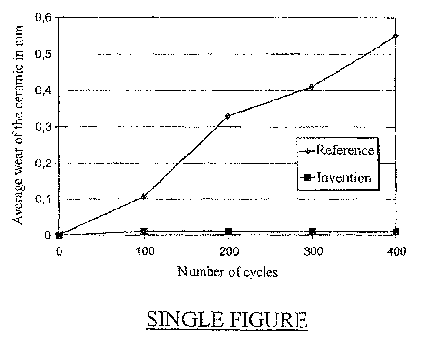
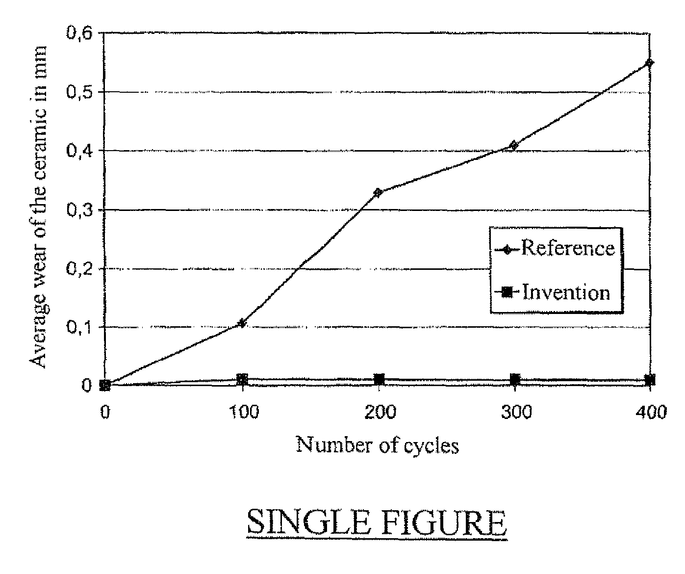
[0033]Thus, the ceramic element located between the electrodes of the spark plug can resist the high stresses that it is subjected to during the ionization phase (high pressure, high temperature, presence of chemical agents) and also during the spark phase when the semiconductor is passive but is subjected to thermal and mechanical shocks. These lead to exposure of the particles of the conductive phase located near the electrode interface, in the case of HELV spark plugs using ceramics known in the art, manufactured from starting materials of a relatively similar nature to those of the present invention, but which have not been produced by using the GPS process. The result of the process of the invention is to obtain ceramics that are distinguished from the prior art by a better-controlled microstructure which is less likely to have defects and where the Si nitride has usually reacted more vigorously with the other compounds forming the insulating phase.

Problems solved by technology

However, this practice does not truly correspond to actual fact.
However, if these systems have not been generally adopted on engines, it is because the lifetime of a spark plug comprising these materials becomes very short if used under harsh conditions, namely at high pressures and high temperatures combined with chemical attacks linked to the type of fuel used.
In HEHV spark plugs, it is the wear of the electrodes which limits the lifetime of the spark plugs whereas in HELV spark plugs, the ceramic wears out substantially before the electrodes, and it is this that limits their lifetime.

Method used


Image

  • Process for the preparation of a sintered ceramic spark plug
  • Process for the preparation of a sintered ceramic spark plug

Examples


Embodiment Construction

[0036]Preferred examples of conductive phases that can be used within the scope of the invention may include SiC and MoSi2 which have excellent thermo mechanical properties. SiC has excellent resistance to oxidation, in particular at temperatures of approximately 650° C. It will be observed that MoSi2 tends to oxidize markedly between 300° C. and 700° C. to form silica and MoO3, of which the mesh volume is much higher than that of MOSi2, which in the long term results in cracking of the parts. But this phenomenon does not occur at very high temperatures (1,100° C. and above), because the protective layer of silica formed prevents the abrupt formation of MoO3.

[0037]The insulating phase comprises one or more modified silicon ox nitrides obtained during sintering from, for example, Si3N4, Y2O3 and MgO, and from free Si3N4 representing a portion of the Si3N4 initially present in the pure state in the mixture, and which has not reacted with the oxides during sintering by the GPS process....


PUM

PropertyMeasurementUnit
porosityaaaaaaaaaa
porosityaaaaaaaaaa
pressureaaaaaaaaaa

Abstract

Process for the preparation of a ceramic wherein: 50% to 75% by weight of a compound intended to form a conductive phase, and 25% to 50% by weight of one or more materials allowing the formation of insulating phases composed of silicon nitride and modified silicon oxynitride are mixed in a receptacle containing a liquid after a thermal treatment leading to sintering of the ceramic; this mixture is subjected to grinding, drying and sieving operations; this mixture is pressed; and this mixture is sintered so as to obtain a ceramic with a porosity of between 0 and 30%. The sintering is carried out under a pressure of at least 50 bar of a gas which is inert towards the constituents of the mixture. Ceramic thus obtained and spark plug comprising it.

Description

TECHNICAL FIELD[0001]The invention relates to the field of spark plugs, and more particularly that of semiconductor ceramics used in the manufacture of high-energy low-voltage spark plugs.BACKGROUND OF THE INVENTION[0002]It is known that spark plugs, in particular for gas turbines and jet engines, may be of two types:[0003]high-energy high-voltage (HEHV) spark plugs, of which the operating voltage is approximately 20 kV;[0004]high-energy low-voltage (HELV) spark plugs, of which the operating voltage is approximately 2 to 3 kV; these are capable of providing energy of some tenths of a Joule to several Joules.[0005]HELV spark plugs comprise a material such as a cermet between their electrodes, so that the application of a sufficient voltage between these electrodes results in the passage of a spark.[0006]The behavior of the material during the different phases of the spark has been analyzed as being as follows:[0007]Firstly, the cermet is active during the ionization phase which corre...

Claims


Application Information

Patent Timeline
Patent Type & Authority Patents(United States)
IPC IPC(8): H01B1/04F02P9/00F02M57/06
CPCC04B35/565C04B35/58092C04B35/584C04B35/597H01T13/38C04B2235/3206C04B2235/3217C04B2235/3224C04B2235/3225C04B2235/3873C04B2235/80C04B2235/3208
Inventor JANKOWIAK, AURELIENBLANCHART, PHILIPPETRENIT, FREDERIC
Owner AEVA
Why Eureka
Try Eureka