Frequency conversion mixer

a frequency conversion and mixer technology, applied in the direction of instruments, electric/magnetic computing, computation using denominational number representation, etc., can solve the problems of difficult commercialization and popularization of products, the size of components becomes smaller, and the inability to implement lumped elements using millimeter waves, etc., to improve conversion gain and noise characteristic, and improve conversion gain

Inactive Publication Date: 2011-09-13
ELECTRONICS & TELECOMM RES INST +1
View PDF5 Cites 13 Cited by
  • Summary
  • Abstract
  • Description
  • Claims
  • Application Information

AI Technical Summary

Benefits of technology

[0006]The present invention provides a frequency conversion mixer, which increases a conversion gain and improves noise characteristic. To improve a conversion gain and noise characteristic, the inverter structure and the switched biasing technique are used, respectively.
[0007]The present invention also provides a frequency conversion mixer, which can decrease an occupied area even while improving conversion gain and noise characteristic. Generally, a frequency conversion mixer operating on millimeter wave needs many inductors to improve high frequency characteristics such as a high gain, a wideband gain, and a low noise figure. The present invention provides a frequency conversion mixer, which uses only one inductor. Therefore, an occupied area is decreased rather than previous works.
[0008]Embodiments of the present invention provide a frequency conversion mixer including: a transconductance stage receiving a Radio Frequency (RF) signal, and providing a current corresponding to a voltage of the RF signal; a switching stage switching the current which comes out from the transconductance stage in response to a local oscillation signal, for down converting the RF signal into an intermediate frequency (IF) signal; a load stage connected between the switching stage and a supply voltage terminal; a current bleeding circuit connected parallel with the switching stage, especially, embodying an inverter structure with transconductance stage to obtain not only a current bleeding effect but also a current reuse effect; one resonant inductor between differential outputs of the transconductance stages, reducing noise which is generated in parasitic capacitance at node between the transconductance stage and the switching stage and also improving the gain response; and a bias stage connected between the transconductance stage and a ground terminal, having at least one current source for allowing a stable bias current.
[0010]In other embodiments, the current bleeding stage may increase a conversion gain of the frequency conversion mixer.

Problems solved by technology

Generally, the size of a component becomes smaller when implementing a system because a millimeter wave has a very short wavelength, and thus a millimeter wave cannot be used for the implementing of a lumped element.
On the other hand, it is difficult to commercialize and popularize a product because of the relatively high cost of production.

Method used


Image

  • Frequency conversion mixer
  • Frequency conversion mixer
  • Frequency conversion mixer

Examples


Embodiment Construction

[0019]Preferred embodiments of the present invention will be described below in more detail with reference to the accompanying drawings. The present invention may, however, be embodied in different forms and should not be constructed as limited to the embodiments set forth herein. Rather, these embodiments are provided so that this disclosure will be thorough and complete, and will fully convey the scope of the present invention to those skilled in the art.

[0020]Hereinafter, it will be described about an exemplary embodiment of the present invention in conjunction with the accompanying drawings.

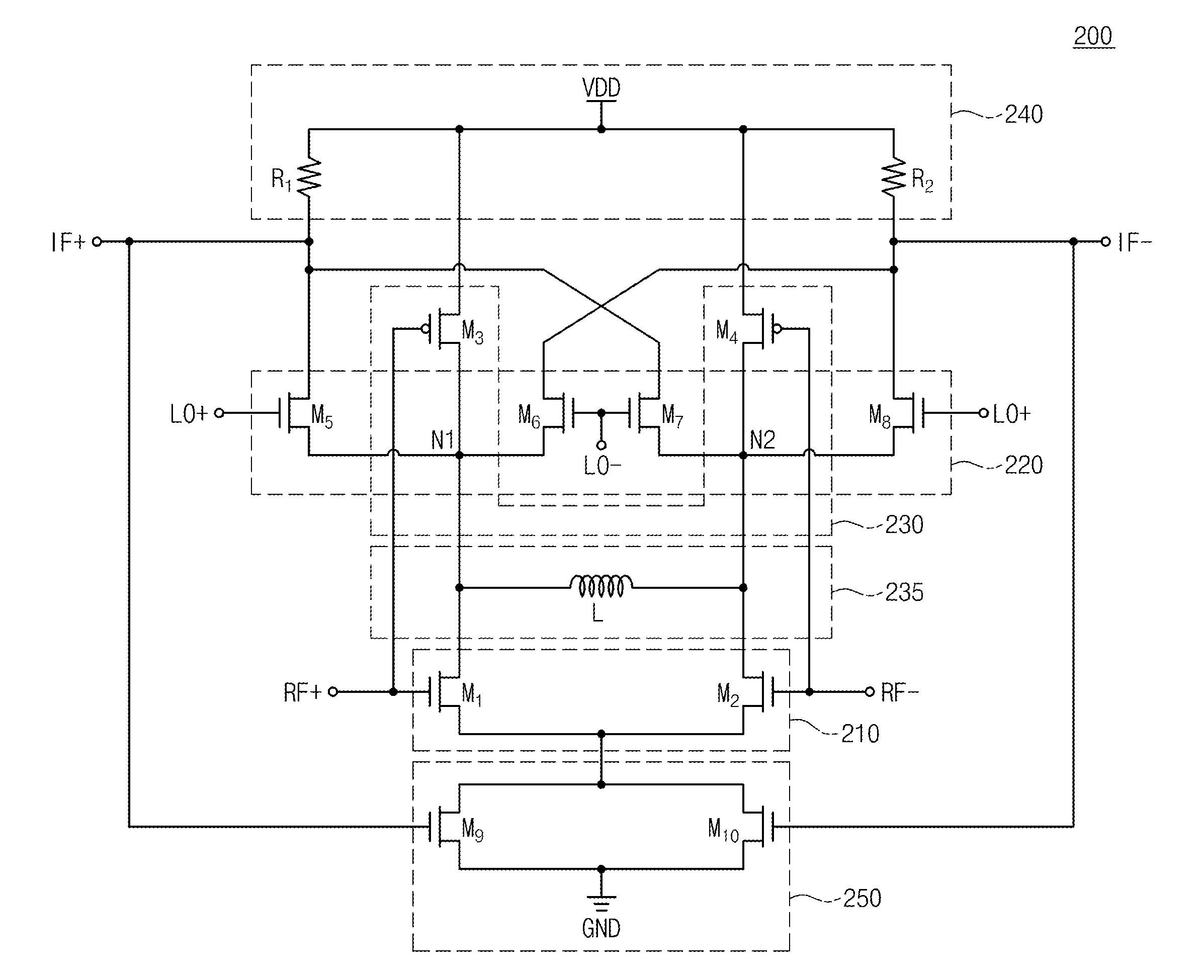
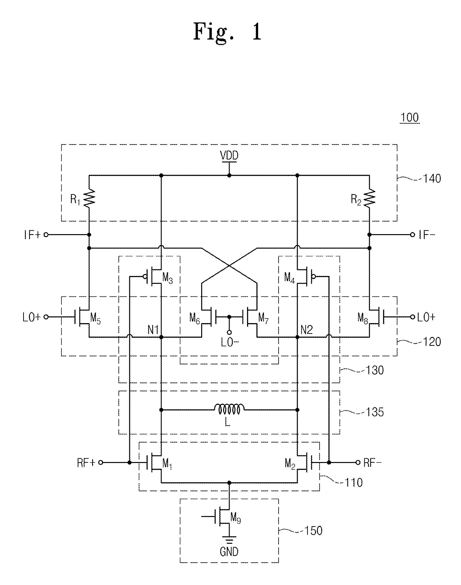
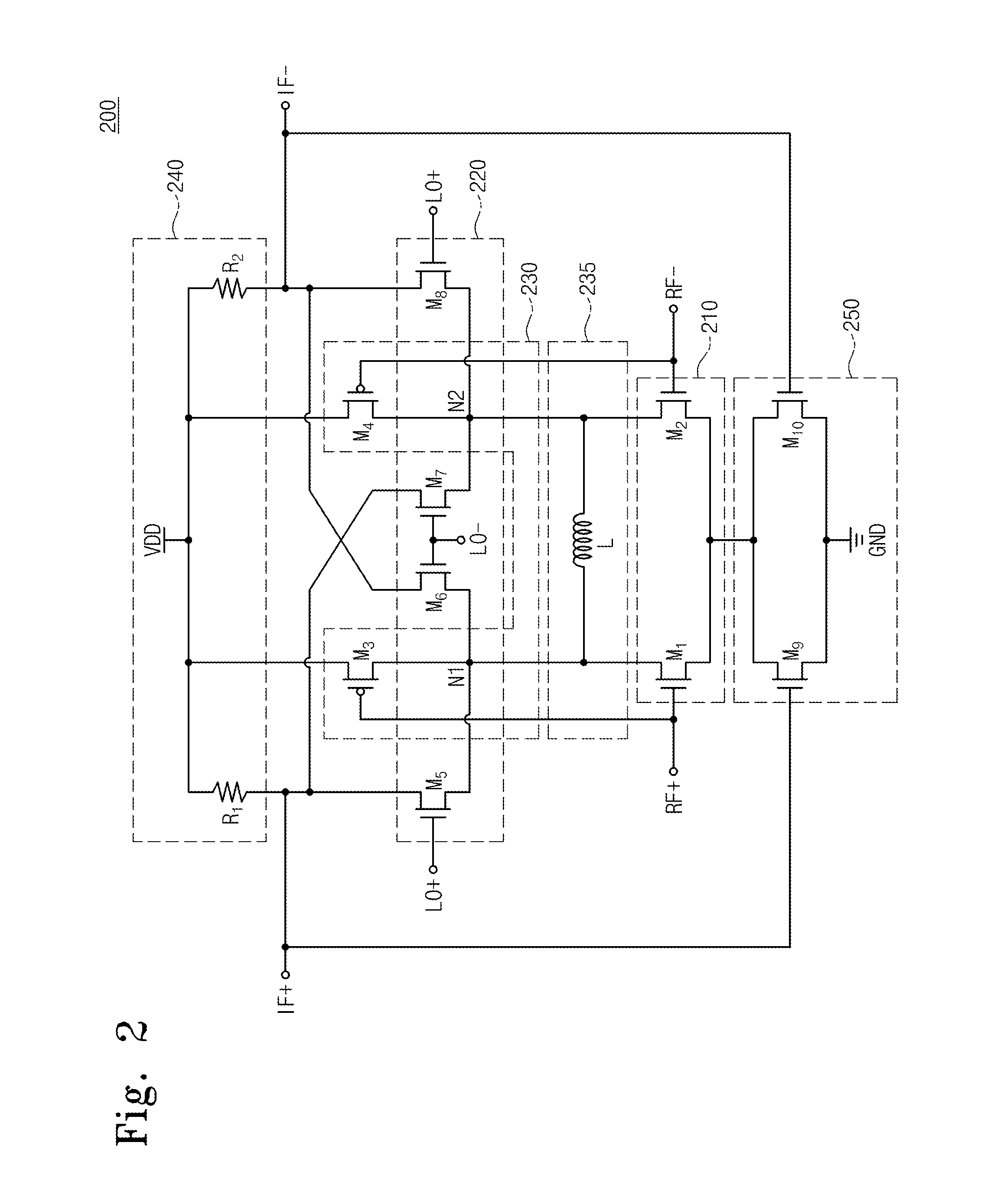
[0021]FIG. 1 is a diagram illustrating a frequency conversion mixer according to an embodiment of the present invention.

[0022]Referring to FIG. 1, a frequency conversion mixer 100 according to an embodiment of the present invention includes a transconductance stage 110 which receives a Radio Frequency (RF) signal, a switching stage 120 which mixes the received RF signal with a local oscillati...


PUM


Abstract

Provided is a frequency conversion mixer. The frequency conversion mixer includes a transconductance stage, a switching stage, a load stage, a current bleeding circuit, and a bias stage. The transconductance stage receives an RF signal, and outputs a current corresponding to a voltage of the RF signal. The switching stage switches the current which is outputted from the transconductance stage in response to a local oscillation signal, for frequency conversion the RF signal into an intermediate frequency (IF) signal. The load stage is connected between the switching stage and a supply voltage terminal. The current bleeding circuit is connected parallel with the switching stage, especially, embodying inverter structure with transconductance stage to get not only current bleeding effect but also current reuse effect, and one resonant inductor for reducing noise which is generated in parasitic capacitance at node between transconductance stage and switching stage. The bias stage is connected between the transconductance stage and a ground terminal, and has the switched biasing technique for allowing not only the stable bias current but also lowering the flicker noise.

Description

CROSS-REFERENCE TO RELATED APPLICATIONS[0001]This U.S. non-provisional patent application claims priority under 35 U.S.C. §119 of Korean Patent Application No. 10-2009-0127219, filed on Dec. 18, 2009, the entire contents of which are hereby incorporated by reference.BACKGROUND OF THE INVENTION[0002]The present invention disclosed herein relates to a frequency conversion mixer.[0003]A millimeter wave denotes an electromagnetic wave having the wavelength of a millimeter unit. This corresponds to a frequency of 30 to 300 GHz in terms of a frequency band. To provide a description on the trend of a millimeter-wave frequency band to date, a frequency band of 20 to 40 GHz is currently being extended for fixed and mobile on the basis of advanced technologies in satellite communication and military communication.[0004]Generally, the size of a component becomes smaller when implementing a system because a millimeter wave has a very short wavelength, and thus a millimeter wave cannot be used f...

Claims


Application Information

Patent Timeline
Patent Type & Authority Patents(United States)
IPC IPC(8): G06G7/12
CPCH03D7/1441H03D7/1458H03D2200/0084H03D2200/0043H03D2200/0025H03D7/00
Inventor KANG, YUN-MOYUN, TAE-YEOULAN, HEE-WOOKIM, CHANG SUNROH, YEA CHULCHOI, SEONG HOON
Owner ELECTRONICS & TELECOMM RES INST
Why Eureka
Try Eureka