
Portable microderm abrasion device

a microderm and abrasion technology, applied in the field of skin treatment system, can solve the problems of skin damage, high operating cost, and high operating cost, and achieve the effects of convenient operation and service, convenient overtreatment of skin, and convenient operation and maintenan

Inactive Publication Date: 2011-09-27
BIORENEW LABS
View PDF12 Cites 35 Cited by
  • Summary
  • Abstract
  • Description
  • Claims
  • Application Information

AI Technical Summary

Benefits of technology

A further advantage of the invention is that the grit supply cartridge and waste collection cartridges are separate units. They are detachable from the housing independently of each other, but fit together in the housing in a compact, cooperative fashion. Both the grit supply cartridge and the waste collection cartridge are configured with unique, interactive couplings to each other and to the housing of the device so that a user is much more likely to purchase refill grit supply and waste collection cartridges from the original manufacturer of the device.
is that the grit supply cartridge and waste collection cartridges are separate units. They are detachable from the housing independently of each other, but fit together in the housing in a compact, cooperative fashion. Both the grit supply cartridge and the waste collection cartridge are configured with unique, interactive couplings to each other and to the housing of the device so that a user is much more likely to purchase refill grit supply and waste collection cartridges from the original manufacturer of the device.
The primary object of the present invention is to provide a safer, more reliable, and economical device for creating microabrasions on the skin, as well as such a device which is easier to operate and service than conventional microderm abrasion machines.
The microderm abrasion device of the invention preferably is provided with safety features that are built in and which are not present in prior art devices. Serious complications can arise from the over treatment of the skin of a subject with conventional microderm abrasion systems and other types of skin treatments that use a stream of abrasive material to abrade the skin. Presently an operator of a conventional device can easily over treat skin by allowing the abrasive stream to impact the same area of the skin for an excessive length of time. As a consequence, impacting, abrasive particles dig too deeply into the skin, thereby causing pain and creating discoloration.
The preferred embodiments of the invention incorporate several alternative mechanisms that prevent or reduce the likelihood of excessive skin abrasion. Possible safety mechanisms include, but are not limited to, detection and control arrangements that automatically halt treatment if a possibility of over treatment is detected, or a warning system to alert the operator of an impending unsafe condition. The warning system can be audible, visual, or tactile. Treatments can be interrupted for safety reasons by reducing or relieving the suction entirely, interrupting the flow of the abrasive media, or shutting down electrical power to the vacuum pump until the threat of over treatment is reduced. Another way of reducing risk is to reduce the flow rate or density of the abrasive material.
The system of the present invention can detect the existence of a threat by measuring the sustained time period during which suction is applied to the skin (e.g., the wand has not been lifted from the skin). Alternatively, movement of the treatment wand can be monitored to detect when it has remained static too long at a specific skin location and thus should be moved to a new, untreated area. If the wand remains static for too long a period, suction can be halted, reduced, or the intensity of treatment can otherwise be diminished. The intensity of treatment can be reduced or halted entirely through a variety of mechanical, electrical, or fluid operating mechanisms.

Problems solved by technology

While conventional microderm abrasion devices do perform their intended function, they present considerable drawbacks.
One problem of such conventional systems is that, while the crystals are being strayed against the skin, the operator must keep the wand in constant motion to avoid over-treatment on a specific area.
This is a safety issue that makes the treatment depth very operator dependent.
If the operator applies the wand in such a manner that crystals are sprayed against the same area of the skin for too long a time, skin damage can occur.
If the operator does not spray the crystals long enough, exfoliation is inadequate.
Another problem with conventional microderm abrasion devices is that they are highly susceptible to clogging.
However, due to the narrow and convoluted passageways through which the crystals pass, there is a high incidence of clogging of the crystals in the line.
This is usually due to clumping of crystals or the presence of oversized debris in the crystals.
Once clogging occurs it can be a difficult, expensive and time consuming process to unclog the system.
A further disadvantage of conventional microderm abrasion systems is that the manufacture and repair of these machines and the provision supply parts is expensive.
When clogging occurs it is often difficult to locate and clear the obstruction.
A lay person is often unable to repair the machine.
Even in those devices in which the crystal supply container is disposable, it is often difficult to access and replace by a lay person.
A further disadvantage of conventional system is that, when a consumer purchases a microderm abrasion system, the purchaser will often elect to purchase replacement crystals from a supplier other than the original equipment manufacturer.
This causes a loss of revenue to the manufacturer, and also contributes to product malfunctions, which are then blamed upon the manufacturer.

Method used


Image

  • Portable microderm abrasion device
  • Portable microderm abrasion device
  • Portable microderm abrasion device

Examples


Embodiment Construction

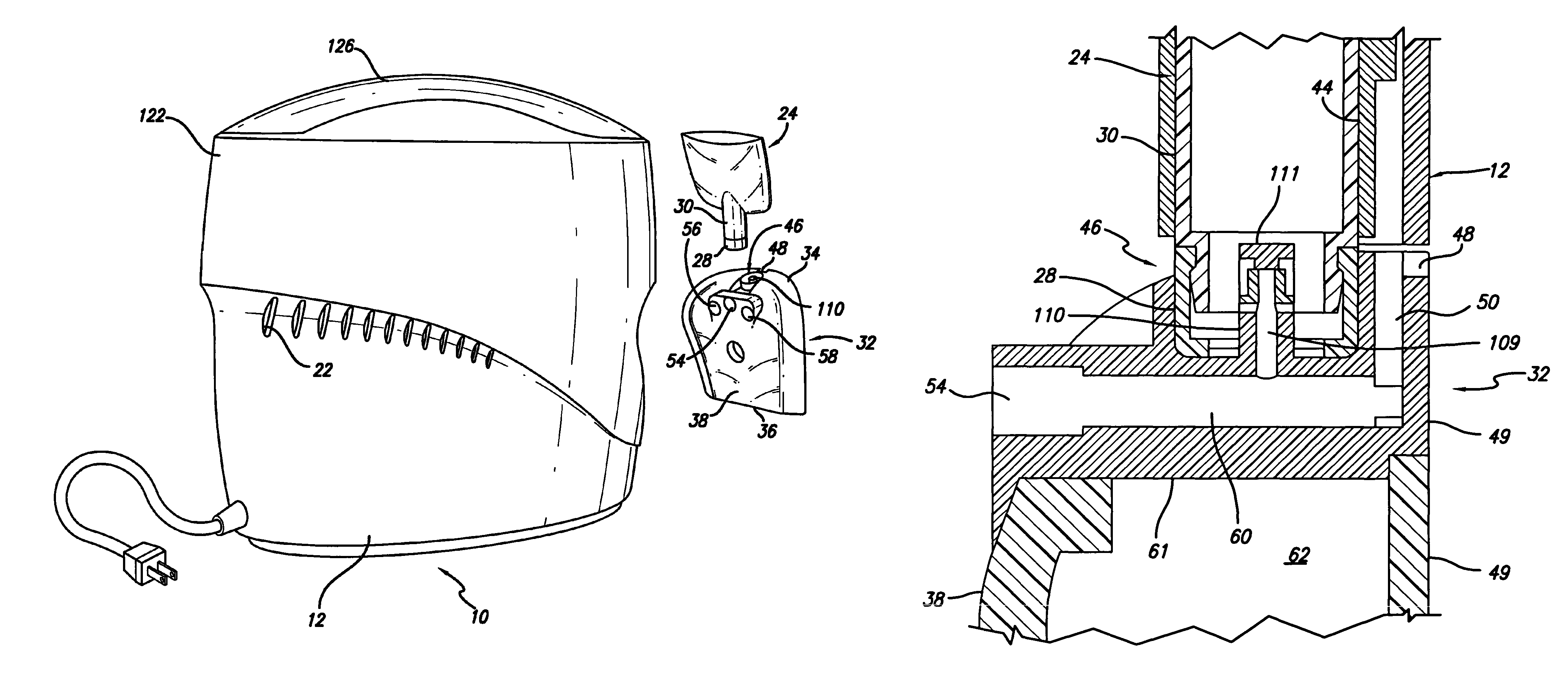
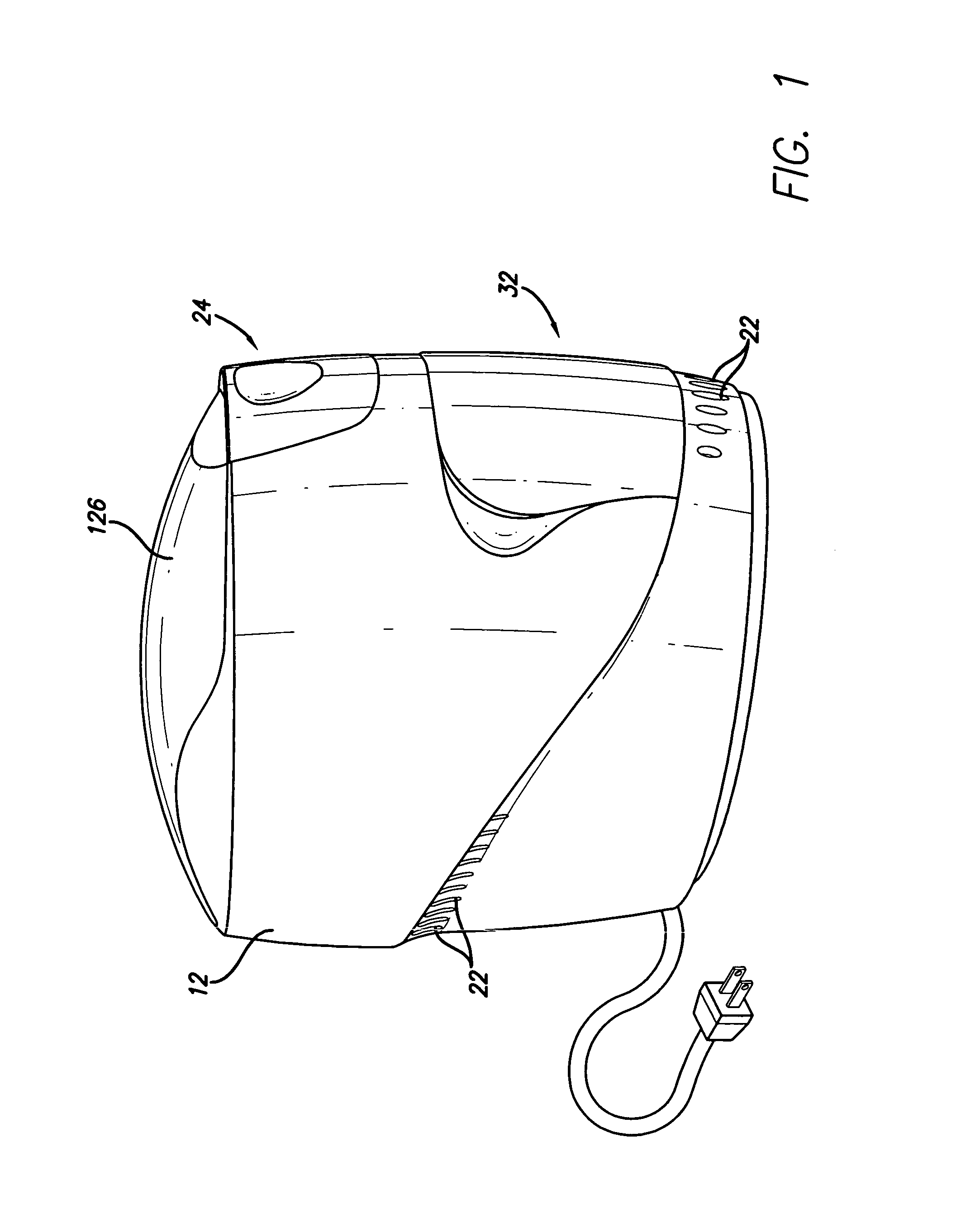
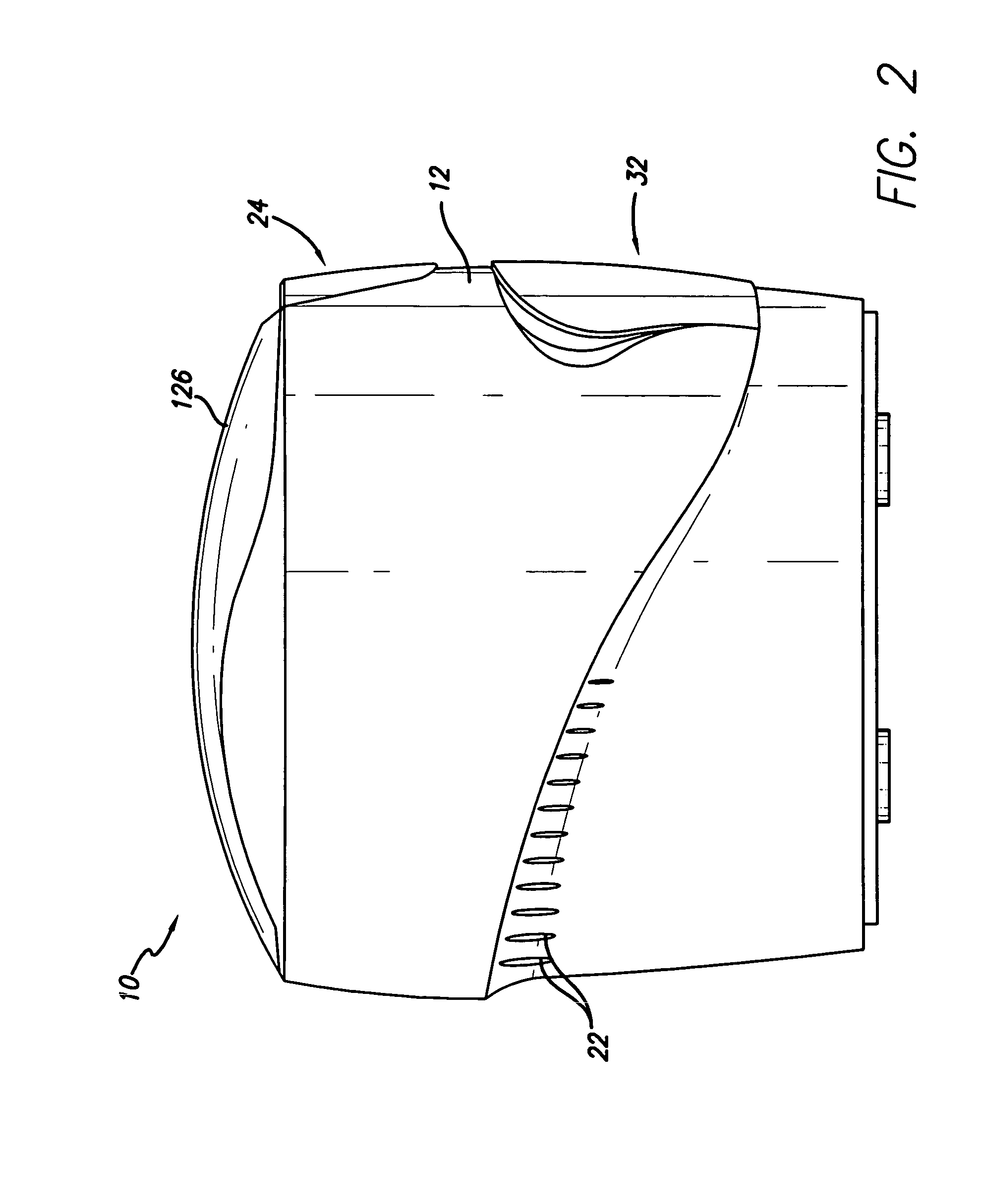
FIGS. 1, 2, and 10, for example, illustrate a portable microderm abrasion device indicated generally at 10 that is comprised of a hollow casing or housing 12 with a lid 126 on its top and supporting rubber feet 13 on its bottom. Within the housing 12 there is an electrically operated motor 14, and an air pump 16 operated by the motor 14. The electric motor 14 is a conventional one hundred twenty volt, alternating current motor, while the air pump 16 is also conventional. The motor 14 and the air pump 16 are partially visible in the broken away view of FIG. 10. The air pump 16 has an air suction port 18 and an air exhaust port 20 that exhausts air into the hollow interior of the casing 12. Air is discharged from the interior of the housing 12 through vent openings 22.

The microderm abrasion unit 10 has a hollow exfoliation grit supply cartridge 24 that is removably located within the housing 12 and which has a grit discharge opening 26, visible in FIG. 19. The discharge opening 26 is ...


PUM


Abstract

A portable microderm abrasion device is comprised of a hollow housing containing an electric motor that operates an air pump having air suction and air exhaust ports. A hollow, disposable exfoliation grit supply cartridge is removably located within an upper bay, while a separate hollow, disposable waste collection cartridge is also located within a lower bay in the housing directly beneath the grit supply cartridge. The two cartridges are separately removable from the housing. Grit from the supply cartridge is mixed with air drawn by a vacuum created by the air pump into a grit entrainment duct located within the waste collection cartridge and carried to a movable wand. A particulate filter located in the waste collection cartridge allows air, but prevents solid waste material, from being discharged to ambient atmosphere. Safety features include a timer and / or a motion sensor to reduce or cut off vacuum in the line if the grit dispensing and retrieval tip of the wand remains in a static condition or exerts a vacuum for too long a period of time upon the skin of the subject.

Description

BACKGROUND OF THE INVENTION1. Field of the InventionThe present invention relates a skin treatment system in which a mechanical device is used to apply light abrasive material to the skin of a person undergoing treatment. The process is often termed microderm abrasion, but is also referred to by other terms such as, skin peeling and exfoliation.2. Description of the Prior ArtMicroderm abrasion is a procedure that may be performed, for example, to exfoliate layers of a person's skin for cosmetic or other reasons. During the procedure very small particulate crystals having light abrasive characteristics are supplied in a first container. A vacuum air flow is then used to entrain the crystals in air and apply them onto the skin of a person through an application wand. As the wand sprays crystals against the skin of the subject, the crystals, along with dead skin cells are then vacuumed by the wand and returned through a separate hose and deposited in a second container to be discarded....

Claims


Application Information

Patent Timeline
IPC IPC(8): A61B17/50
CPCA61B17/545
Inventor DAVID, JONATHAN EDWARDBOLEN, DALE W.
Owner BIORENEW LABS
Learn More