Protected resonator

a resonator and protection technology, applied in the field of thin film bulk acoustic wave resonators, can solve the problems of long-term frequency aging, difficult integration in a product, and easy damage to the mounting of the resonator, and achieve excellent inertial resistan

Inactive Publication Date: 2011-10-04
CYMATICS LAB CORP
View PDF9 Cites 22 Cited by
  • Summary
  • Abstract
  • Description
  • Claims
  • Application Information

AI Technical Summary

Benefits of technology

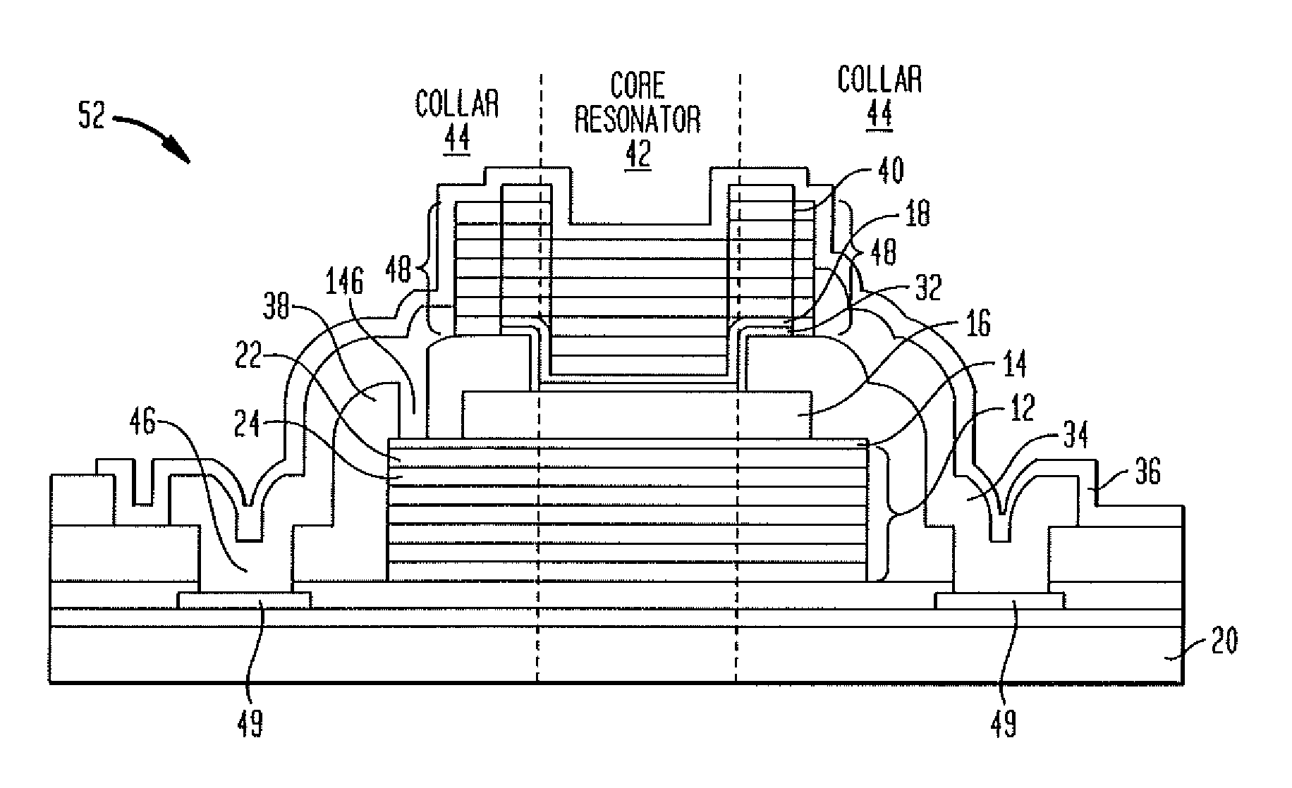
[0013]The present invention is directed to a bulk acoustic wave resonator structure that isolates the core resonator from both environmental effects and aging effects. The structure protects against contamination, package leaks, and changes to the piezoelectric material due to external effects like ionizing radiation and package stress, while still providing excellent inertial resistance. In preferred embodiments of the present invention the structure has one or more protective elements that limit aging effects to at or below a specified threshold. That threshold is expressed herein as a shift in the impedance response of the resonator as a function of frequency that is at or below a certain value. As one skilled in the art will appreciate, an acoustic resonator device has an impedance value for each frequency value. As the resonator ages, the impedance value associated with a frequency value may change over time. Thus, the impedance value (Z) associated with a frequency f for the acoustic resonator as designed may change to the value Zi over time. The present invention limits the rate of the change of frequency to at or below a certain level.
[0016]According to the embodiments described herein, mitigation of the effects that cause aging is more than simply minimizing frequency drift of the series or parallel resonance. For example, series resonance frequency depends on the acoustic path and any parasitics. Therefore the electromechanical coupling coefficient and dielectric constant of the resonator materials (and changes thereto over time) play no role in determining the series resonance frequency, and any subsequent drift in that frequency.
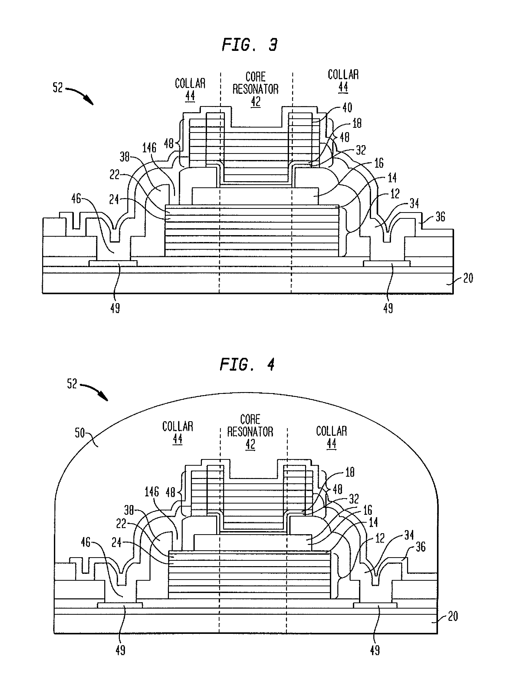
[0018]The resonator is protected from the effects of degradation of the material due to environmental and / or aging processes, by providing protective element that is a collar of material, in one particular embodiment a piezoelectric material, around the core resonator so that perimeter and edge-related environmental and aging phenomena are kept away from the core resonator.
[0019]In certain embodiments the resonator is protected against the effect of contamination on the surface by surrounding it on all sides by a protective element that is a plurality of energy-confining Bragg layers.

Problems solved by technology

The current methods of packaging are either high profile (the case with quartz), which makes them difficult to integrate in a product; or they encapsulate thin-film structures like released inertial resonators or FBARs that are susceptible to other forms of instability such as acceleration or shock.
Stress introduced by packaging and transmitted to the crystal causes long-term frequency aging.
The current methods of mounting of the resonator are susceptible to inertial and thermal fatigue, hence aging.
None of these approaches, however, address the protection of the crystal and / or electrode material itself.
The current approaches do not protect the crystal or electrode material from environmental effects, including aging.

Method used


Image

  • Protected resonator
  • Protected resonator
  • Protected resonator

Examples


embodiment 66

[0063]For certain applications, stresses originating from the wafer itself are significant enough to justify released (FBAR) structure even though these structures exhibit decreased inertial resistance. FIGS. 10 and 11 illustrate another alternate embodiment 66. The released FBARs have the collar 44 and spacer 38 that protect the core resonator 42. The FBARs are covered with a cap 60 structure as described above for FIG. 9.

[0064]The structures illustrated in FIGS. 10 and 11 are formed as follows. A sacrificial release layer is deposited and patterned such that it remains under the device region 42. On the substrate 20 is formed a temperature compensating layer 32, lower electrode 14, piezoelectric 16 material, and upper electrode 18. The upper electrode 18 is patterned by photolithography and etching. The piezoelectric 16 material, the lower electrode 14, and the temperature compensation layer are all patterned (preferably with the same mask) using photolithography and a sequence of...

embodiment 74

[0070]FIG. 12 is a cross section view of an alternate embodiment 74. This embodiment is an inverted SMR with a core resonator 42, collar 44, both of which are encapsulated under a cap 40 that is constructed as a Bragg reflector. The structure 74 has a lower electrode 14, a piezoelectric 16 layer, and an upper electrode 18. A temperature-compensating layer is optional and not illustrated. The cap 40 formed over the resonator structure consists of an inner protective layer 62 and a seal layer 64. The seal layer 64 is configured as an energy-confining upper Bragg reflector. As previously described such a layer has multiple pairs of layers, each pair having a high acoustic impedance layer 24 and low acoustic impedance layer 22. As described above, each of these materials has a thickness equal to a quarter acoustic wavelength of the operational mode in the material. Individual reflector layers are not shown but illustrated as one monolithic layer 40. As with other embodiments, this embod...


PUM


Abstract

A bulk acoustic wave resonator structure that isolates the core resonator from both environmental effects and aging effects. The structure has a piezoelectric layer at least partially disposed between two electrodes. The structure is protected against contamination, package leaks, and changes to the piezoelectric material due to external effects while still providing inertial resistance. The structure has one or more protective elements that limit aging effects to at or below a specified threshold. The resonator behavior is stabilized across the entire bandwidth of the resonance, not just at the series resonance. Examples of protective elements include a collar of material around the core resonator so that perimeter and edge-related environmental and aging phenomena are kept away from the core resonator, a Bragg reflector formed above or below the piezoelectric layer and a cap formed over the piezoelectric layer.

Description

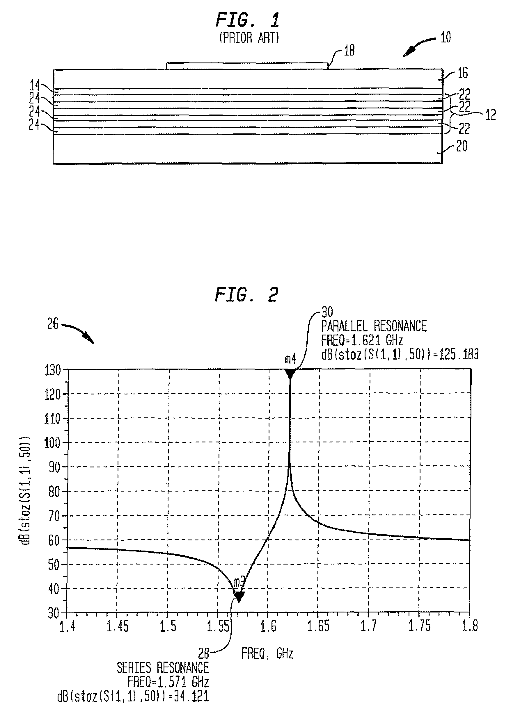
FIELD OF THE INVENTION[0001]High-stability resonators and, more particularly, thin-film bulk acoustic wave resonators that are largely immune to environmental effects and aging are disclosed herein.BACKGROUND OF THE INVENTION[0002]The response of a bulk-acoustic wave resonator (FBARs, SMRs, HBARs, etc.) exhibits long term drift in its characteristics, particularly in frequency. This time-dependent long-term change is known as drift of the resonator. The drift is caused by both intrinsic and extrinsic factors and the intrinsic instability is often called as aging of the resonator. Aging occurs even when external environmental factors are kept constant. An example of an SMR structure from the prior art is illustrated in FIG. 1.[0003]In the literature, Walls and Vig, “Fundamental Limits on the Frequency Stabilities of Crystal Oscillators,” IEEE Transactions On Ultrasonics, Ferroelectrics, And Frequency Control, 42(4):576-589, July 1995 (referred to herein as Walls and Vig, 1995) and Vi...

Claims


Application Information

Patent Timeline
Patent Type & Authority Patents(United States)
IPC IPC(8): H01L41/08
CPCH03H9/02086H03H9/02102H03H9/02133H03H9/02149H01L41/0533H03H9/1007H03H9/105H03H9/175H03H9/0557H10N30/883
Inventor SINHA, RAJARISHICARLEY, L. RICHARDCHOMAS, LOUIS CALEYSAFAR, HUGO
Owner CYMATICS LAB CORP
Why Eureka
Try Eureka