Method for operating a propulsion system of a watercraft

a technology for watercraft and propulsion system, which is applied in marine propulsion, vessel auxillary drive, vessel construction, etc., can solve the problems of connecting device damage, potential imminent damage, and tear or destruction of energy transfer connection device or components to which it was attached, and achieves the effect of reducing the risk of damage to the connected devi

Inactive Publication Date: 2011-10-25
BRUNSWICK CORPORATION
View PDF29 Cites 24 Cited by
  • Summary
  • Abstract
  • Description
  • Claims
  • Application Information

AI Technical Summary

Benefits of technology

[0036]Various types of marine transmissions can be used in conjunction with various preferred embodiments of the present invention. These transmissions usually comprise a single forward gear, a single reverse gear, and a neutral gear position. Certain types of marine transmissions, which are very familiar to those skilled in the art of marine propulsion systems, further comprise a dog clutch mechanism that allows the dog clutch to slide in forward and reverse directions parallel to the propulsion shaft to link the propulsion shaft in torque transmitting relation with either a forward or a reverse rotating bevel gear that is driven by a gear attached to a generally vertical driveshaft. It should be understood that the particular configuration of the transmission is not limiting to the present invention and many other different types of transmission can be employed to control the interaction of the various components used to transmit torque from the crankshaft of an engine to the propeller. The primary purpose of the marine transmission which is used in conjunction with the various preferred embodiments of the present invention is to allow the operator of the watercraft to connect the crankshaft of the engine to the propulsion shaft to result in forward and reverse rotation of the propellers.
[0037]The step of determining a rotation status of the propulsion shaft can be accomplished in several ways. However, it should be understood that the basic purpose of this step is to decide on whether the propulsion shaft, and the propeller connected to it, is rotating about the propulsion shaft axis or whether it is stationary. A rotating status, in the preferred embodiments of the present invention, indicates that the watercraft is moving or about to begin moving. If the rotation status indicates that the propulsion shaft is not rotating about its axis, the propeller is not providing the thrust which would be likely to cause the watercraft to move. It should not be assumed that, in every embodiment of the present invention, the actual movement or rotation of the propulsion shaft is directly measured or monitored. In many cases, particularly those cases where a microprocessor is used to control the operation of the watercraft, the rotation status of the propulsion shaft can be determined indirectly or inferentially by observing the gear position of the transmission (i.e. forward or reverse) along with the operational status of the engine (i.e. crankshaft turning or engine running). In other applications, observance of certain fluid pressures within the gear case of the drive unit can indicate the rotational condition of the propulsion shaft.
[0038]The energy storage device in preferred embodiments of the present invention is disposed for support on the watercraft and configured to receive energy from a first source of energy and a second source of energy. The first source of energy is located on the shore, most probably at a location near where the watercraft is likely to be docked for extended periods of time. The location...

Problems solved by technology

At a minimum, some connective device can be severely damaged.
Since the recharging of the energy storage components (e.g. flywheel, fuel tanks, capacitors, rechargeable batteries) requires some physical interconnection between an onshore energy source and a mechanism on a watercraft and, in turn, between the mechanism and the energy storage device on the watercraft requires a physical connection that is relatively sturdy, movement away from the dock or marina will tear or destroy the energy transfer connection device or the components to which it was attached.
One situation is the movement or potentially imminent movement of the marine vessel.
Stated even more simply, if the watercraft is connected to some stationary device on shore and the marine vessel is able to move relative to the dock, very serious problems can occur and significant damage is likely to result.
In these circumstances, the battery potential can actually be depleted as the battery attempts to provide the additional required electrical current for the loads.
In addition, the visible surfaces that do not become directly submerged or significantly wetted during normal use of the boat are subject to frequent exposure to splashing during normal use of the marine vessels, particularly pleasure craft.
Although lids and covers can be provided with seals, maintaining the integrity of the seals over time can be quite...

Method used


Image

  • Method for operating a propulsion system of a watercraft
  • Method for operating a propulsion system of a watercraft
  • Method for operating a propulsion system of a watercraft

Examples


Embodiment Construction

[0051]Throughout the description of the preferred embodiment of the present invention, like components will be identified by like reference numerals.

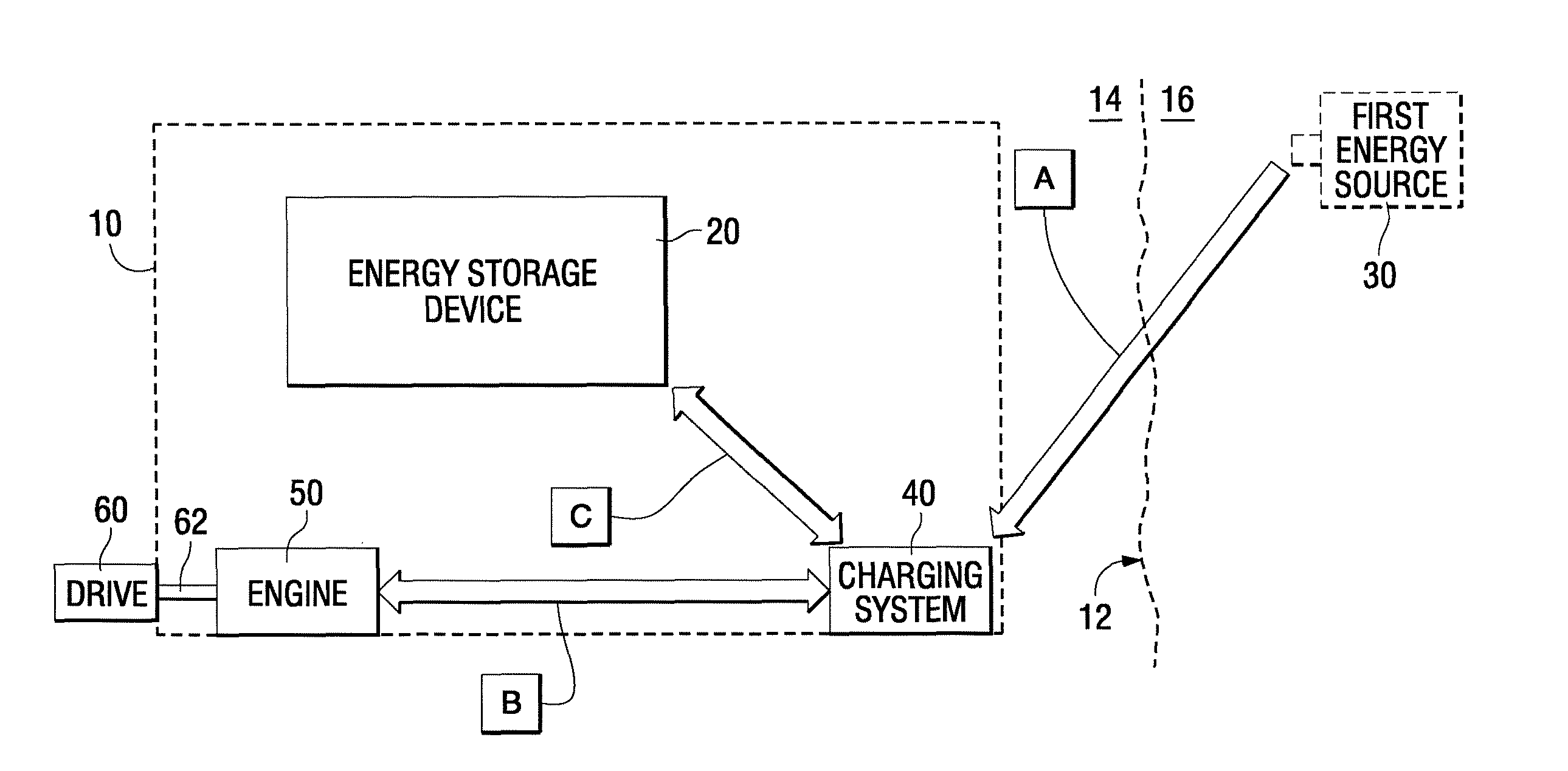
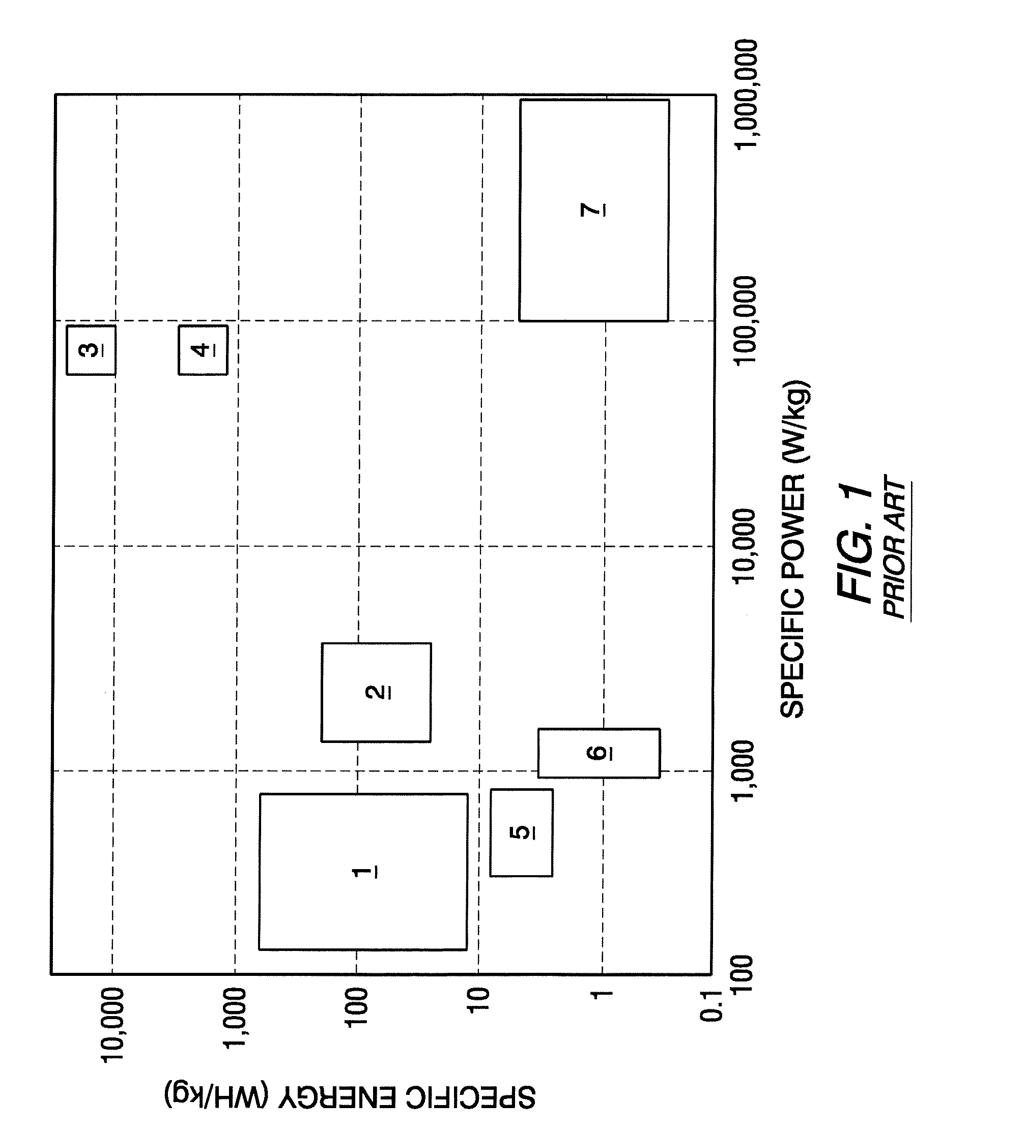
[0052]Recent developments of energy efficient vehicles have led to the development of several commercially viable energy storage systems that are being provided for hybrid electric vehicles (HEV's). The technical advances relating to this field have proceeded at such a pace that it is extremely difficult to predict the type of energy storage device that will be used in any particular hybrid watercraft. As described in the website of the College of Engineering of San Diego State University, potential energy storage devices must be reviewed and analyzed based on their specific energy and specific power. This information is available on the Internet at http: / / www.engineering.sdsu.edu / ˜hev / energy.html along with interesting and educational graphs, charts, and descriptive text. At this time, the types of energy storage devices that appear to...


PUM


Abstract

A hybrid marine vessel is provided with a system that inhibits the movement of the marine vessel under its own power when the marine vessel is connected or recharging to a stationary source of energy on shore. This avoids significant damage that could otherwise occur if the marine vessel moves away or attempts to move away from the dock when connected by a cable or other device to a stationary structure. The system detects a potential connection between the boat and a stationary shore component, such as a source of energy, and inhibits the transmission from being placed in a forward or reverse gear position under those conditions. Similarly, if the boat is already in a forward or reverse gear position, the system inhibits its being placed into a battery recharging mode.

Description

BACKGROUND OF THE INVENTION[0001]1. Field of the Invention[0002]The present invention is generally related to a method for operating a propulsion system of a watercraft and, more particularly, to a technique for controlling the relationship between the connecting and disconnecting of an energy recharging system for the watercraft and how that system interrelates with the control of various components on the watercraft that allow it to move in response to changes in the condition of its transmission and changes in the operating status of its engine.[0003]2. Description of the Related Art[0004]The basic problem toward which the preferred embodiments of the present invention are directed is the avoidance of accidents that can occur if a watercraft is moved relative to a dock while it is physically connected to a recharging system. At a minimum, some connective device can be severely damaged. Since the recharging of the energy storage components (e.g. flywheel, fuel tanks, capacitors, r...

Claims


Application Information

Patent Timeline
IPC IPC(8): B63H21/22
CPCB63H21/20B63J3/00B60L11/005B60L11/14B60L11/16B60L11/1805B60L11/1816B60L11/1877B60L15/20B63H21/21Y02T90/127B63H23/08B63H2021/205B63J2003/002B63J2003/043Y02T70/5209Y02T70/5236Y02T90/38Y02T90/46Y02T10/7275Y02T10/70B60L2200/32B60L2210/30B60L2240/423B60L2240/425B60L2250/10Y02T10/7077Y02T10/7005Y02T10/705Y02T10/7241Y02T10/7022Y02T10/642Y02T90/14Y02T10/7072B60L53/14B60L50/40B60L50/16B60L50/30B60L50/52B60L50/66Y02T10/64Y02T10/72Y02T70/50Y02T90/40Y02T90/12
Inventor WYANT, JOHN W.
Owner BRUNSWICK CORPORATION
Why Eureka
Try Eureka