Rotary fluidized bed device and method for using said device

a fluidized bed and rotating technology, applied in the direction of drying, lighting and heating equipment, mixers, etc., can solve the problems of fluids becoming very bulky, reducing rotational velocity, and limiting the ability to transfer a significant momentum to solid particles, etc., to achieve good separation, high centrifugal force, and high heat transfer capacity

Active Publication Date: 2011-12-06
DE BROQUEVILLE
View PDF28 Cites 4 Cited by
  • Summary
  • Abstract
  • Description
  • Claims
  • Application Information

AI Technical Summary

Benefits of technology

[0018]The present invention provides for the use of injectors, distributed around the circular wall of a cylindrical chamber also called “circular reaction chamber”, which inject one or more fluids, along the circular wall, in successive layers, in order to form a succession of fluid layers which are superimposed while rapidly rotating inside the reaction chamber, around a central duct which penetrates thereinto or passes through it along its central axis and which is provided with one or more discharge openings through which the fluid can be removed centrally. The circular reaction chamber is traversed by a stream of solid particles which are fed at one of its sides and removed at the opposite side and which are entrained by the fluid in a rapid rotational movement whereof the centrifugal force serves to concentrate them, before they leave the circular reaction chamber, in a dense rotating fluidized bed, which is at least partially supported by the centripetal pressure of these successive fluid layers which extend along the circular wall and which act as fluid pads, reducing the friction of the solid particles against this wall. The fluid is fed by a feed device which may comprise a fluid feed chamber surrounding the circular reaction chamber, the difference in pressure, preferably higher than the average pressure due to the centrifugal force of the rotating fluidized bed against the circular wall, between the feed device and the central duct and the flow rate of the fluid(s) serving to support and make the fluidized bed rotate at a velocity generating a substantial average centrifugal force, preferably higher than three times the force of gravity.
[0037]This method accordingly permits the construction of lightweight, compact, transportable and efficient units, for example for drying cereal grains. It is also suitable for catalytic modifications of fluids at low pressure, like the cracking of light olefins or the dehydrogenation of ethylbezene which, being highly endothermic, require intermediate heatings and catalyst regeneration. It can also be used for the catalytic, bimodal or multimodal copolymerization of particles in suspension in a succession of active fluids of different compositions.

Problems solved by technology

The rotational velocity will decrease rapidly if the angular momentum of rotation is not maintained using rotating mechanical means, with the problems associated with the presence of moving equipment inside the reactor, and / or by the injection of fluid at high velocity, in the direction of rotation of the fluidized bed.
However, when a fluid jet is injected at high velocity into a large reactor, it is rapidly slowed down by its expansion in the reactor, depending on the conditions under which it is injected, thereby limiting its ability to transfer a significant momentum to the solid particles.
This is why, unless other mechanical means are used to rotate the fluidized bed, it is necessary to have a very high fluid flow rate to be able to transfer to the solid particles the momentum necessary to maintain a sufficient rotational velocity to maintain them along the cylindrical wall of the reactor, and if the fluid density is much lower than the density of the particles, the devices for centrally removing these fluids may become very bulky, and may limit the height or length of the reactor.
Accordingly, the removal of the fluid becomes more direct, and this may even cause a reversal of the fluid flow along the central duct, downstream of the discharge openings, and generate turbulence which entrains the solid particles toward the outlet, thereby limiting the possibility of forming a thick and dense fluidized bed inside the cylindrical chamber.
In light of the above, it is clear that the formation of a rotating fluidized bed in a reactor faces various problems.

Method used


Image

  • Rotary fluidized bed device and method for using said device
  • Rotary fluidized bed device and method for using said device
  • Rotary fluidized bed device and method for using said device

Examples


example 1

Conversion of Cracking Gasolines to Light Olefins Using a Device According to the Invention

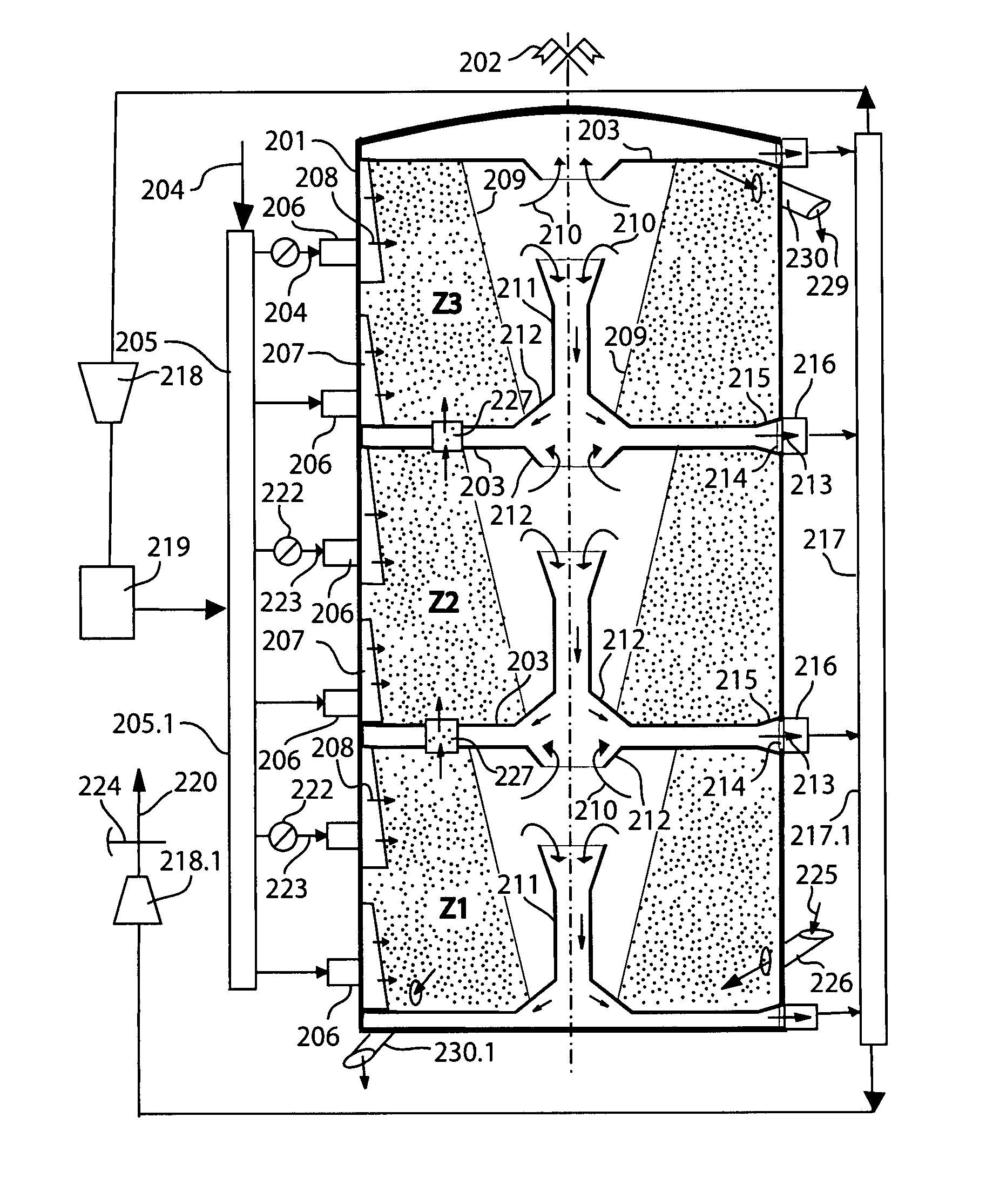
[0273]The cylindrical reaction chamber shown in FIG. 8 may, for information, have a diameter of 1 m, a length of 4.5 m and an average thickness (width) of 0.23 m, giving it a volume of about 2.5 m2. The fluid (100), consisting of cracking gasolines preheated to high temperature, having a density of about 5 kg / m3, at the injection temperature and pressure, is injected at high velocity (for example 200 to 300 m / s, giving a potential pressure of 100 to 200 000 Pa) into the ejector (105) to be superheated to the desired temperature (over 600° C.), at the same time as the recycled fluid it entrains into the furnace (102) and then into the reaction chamber, where they are injected, for example, at a velocity of 60 m / s through 17 injection slits 0.005 m thick, giving a flow rate of about 23 m3 / s, or 400 tonnes per hour. (This high flow rate requires a central duct passing through the reaction chamber...

example 2

Drying of Agricultural Grains Using a Device According to the Invention

[0275]Grains of agricultural origin can be dried according to the diagram in FIG. 9. The reaction chamber or drying chamber may have the same dimensions as those of the above example. In this case, the fresh air (112) is introduced via the tube (8.1), optionally through a moisture condenser (113), to pass through the end of the reaction chamber on the side of the grain outlet (19) in order to heat them while cooling them and completing their drying. This air (11.1) is then sucked out by the centrifugal compressor or fan (108.1) through the line (10.1) and recycled to the reactor via the line (8.2) after having been heated additionally in the heater (102). After having been recycled several times, this air (11.2) is sucked out by the centrifugal compressor or fan (108.2) through the line (10.2) and recycled to the reactor via the line (8.3) after having been heated by the heater (102). After having again been recy...

example 3

Gas Phase Copolymerization of Ethylene and Octene Using a Device According to the Invention

[0279]The gas phase copolymerization of ethylene and octene is only possible if the pressure in the reactor is low, at a maximum no more than a few times the atmospheric pressure, because the octene partial pressure is limited to about 0.2 bar at 70° C. At these pressures, the quantity of heat produced by these highly exothermic reactions can only be removed by using relatively inactive catalysts or by diluting the mixture of active gases with an inactive gas to slow down the reaction rate, thereby increasing, the cost of the installation, or by passing such a large quantity of gas through the fluidized bed as to require a rotating fluidized bed, for example according to the diagram shown in FIG. 10.

[0280]The octene can be sprayed in fine droplets (120) into the reaction chamber by the tube (121) passing through the central duct and / or can be fed in gaseous form at the same time as the fresh e...


PUM


Abstract

The present invention relates to a device with a rotating fluidized bed in one or a succession of cylindrical chambers, in which injectors (12), distributed around the fixed circular wall (2) of said cylindrical chamber(s), inject along this wall, in successive layers, one or more fluids (13), which entrain the solid particles (17), passing through this / these chamber(s), in a movement of rapid rotation whereof the centrifugal force concentrates these particles along this wall, thereby forming a fluidized bed rotating around a central duct or a plurality of central ducts (3), through which the fluids are removed. The present invention further relates to a method of catalytic polymerization, drying or other treatments of solid particles in suspension in a rotating fluidized bed or of catalytic conversion of fluids passing through said rotating fluidized bed using a device according to the present invention.

Description

TECHNICAL FIELD OF THE INVENTION[0001]The present invention relates to a device for a rotating fluidized bed and to a device for injecting fluid into this rotating fluidized bed, inside a fixed circular reaction chamber, and to methods of catalytic polymerization, drying, impregnation, coating or other treatments of solid particles in suspension in the rotating fluidized bed, or of cracking, dehydrogenation, or other catalytic conversions of fluids using this device.TECHNOLOGICAL BACKGROUND OF THE INVENTION[0002]Methods in which solid particles are in suspension in a fluid and thereby form a fluidized bed through which this fluid passes are well known. When the fluid is injected tangentially to the side wall of a cylindrical reactor, it can transfer part of its kinetic energy to the solid particles in order to make them rotate, and if the energy transfer is sufficient, this rotational movement produces a centrifugal force which can maintain the solid particles along the wall of the ...

Claims


Application Information

Patent Timeline
Patent Type & Authority Patents(United States)
IPC IPC(8): F27B15/08F27B15/00
CPCB01J8/14B01J8/1881B01J8/36B01J8/384B01J2219/0004B01J2219/182B01J2219/185B01J8/00B01J8/16
Inventor DE BROQUEVILLE, AXEL
Owner DE BROQUEVILLE
Why Eureka
Try Eureka