Open MRI magnetic field generator

a magnetic field generator and open technology, applied in the field of permanent magnet designs, can solve the problems of high cost, limited, and limited use of most whole-body permanent magnet scanners, and achieve the effects of reducing fringe field generation, efficient yoke and return design, and high efficiency and practical design

Active Publication Date: 2011-12-13
LIAN JIANYU +2
View PDF12 Cites 24 Cited by
  • Summary
  • Abstract
  • Description
  • Claims
  • Application Information

AI Technical Summary

Benefits of technology

Accordingly, such an arrangement of permanent magnet arrays has the effect of concentrating the flux generated in the center while minimizing the flux externally. A yoke system further concentrates the flux in the center and minimizes leakage while also being used to support the permanent magnets.
A further means of homogenizing the magnetic field in the center is provided by a pole that forms a constant potential surface to account for manufacturing Tolerance buildups and material inhomogenieties in the permanent magnet (PM) blocks. The pole system's effectiveness is enhanced by the drastically reduced flux generated in it due to the combination of the disk and ring portions of the PM blocks.
Another feature of this invention relates to the composition of the disk PMs that are made of multiple sections each exhibiting slightly different orientations so that flux saturation is minimized and field homogeneity in the imaging region is optimized. Moreover, a ferromagnetic portion is added midway in the disk PMs to reduce mechanical forces and increase the magnetic field in the center.
In yet another preferred embodiment of this invention there is provided a T-section with the main yoke. In one preferred embodiment this ring section is made of a ferromagnetic material and plays the role of a field clamp significantly reducing fringe field generation. In another embodiment this ring section can be a permanent magnet material magnetized substantially in the axial direction and thereby extend the homogeneous field region in the air gap by up to 5 cm or more. The placement of the T-yoke, particularly the ring portion aids in a much more even flux distribution throughout the yoke and return yielding a more efficient yoke and return design.
In a further aspect of this invention the return portion can be placed all the way against the ring portion of the T-yoke and still maintain a highly efficient and practical design without impacting any performance parameters. Such a placement decreases the amount of flux flowing through the top portion of the T-yoke and further reduces its size and weight.

Problems solved by technology

However, magnets based on superconducting coil technology require dual cryogen systems and periodic refilling making them expensive to buy and maintain.
Most whole-body permanent magnet based scanners are still below 0.5 Tesla and are limited in certain important applications that require greater field strengths.
The limitations become severe when the required magnetic field is greater than 0.5 Tesla.
Thus, there is a fundamental limit to how much magnetization these materials can produce and the magnets made from them if they are to be compact in size and weight.
Second, the ferromagnetic structures and in particular the poles will saturate rendering the magnet inoperative.
The main source of the problem in conventional magnets is the poles.
However, for typical whole-body systems, as the magnetic field strength in the air gap is required to be greater than about 0.4 T, the poles start to saturate making them ineffective or leading to designs that become impractical because they have to be made very thick.
At field strengths greater than 0.4 T, a significant part of the magnetic field energy gets concentrated in the poles saturating them and leading to an inefficient design.
Moreover, the abrupt change of direction of magnetic field lines at the pole-air gap interface causes more magnetic energy leakage making the field in the air gap inhomogeneous along with many of the other problems already mentioned.
However, this solution leads to increased inefficiency because the yokes and returns have to be proportionally bigger in order to carry the additional fluxes generated that would otherwise lead to substantial leakage of energy through these structures as well.
In addition to the problems caused by the poles, the yoke and returns are further sources of magnetic energy leakage.
However, this increases the overall size, weight and footprint of the magnet.
However, this is a closed system and doesn't easily lend itself for MRI purposes because the subject under examination needs to be able to go in and out of the sphere.

Method used


Image

  • Open MRI magnetic field generator
  • Open MRI magnetic field generator
  • Open MRI magnetic field generator

Examples


case 2

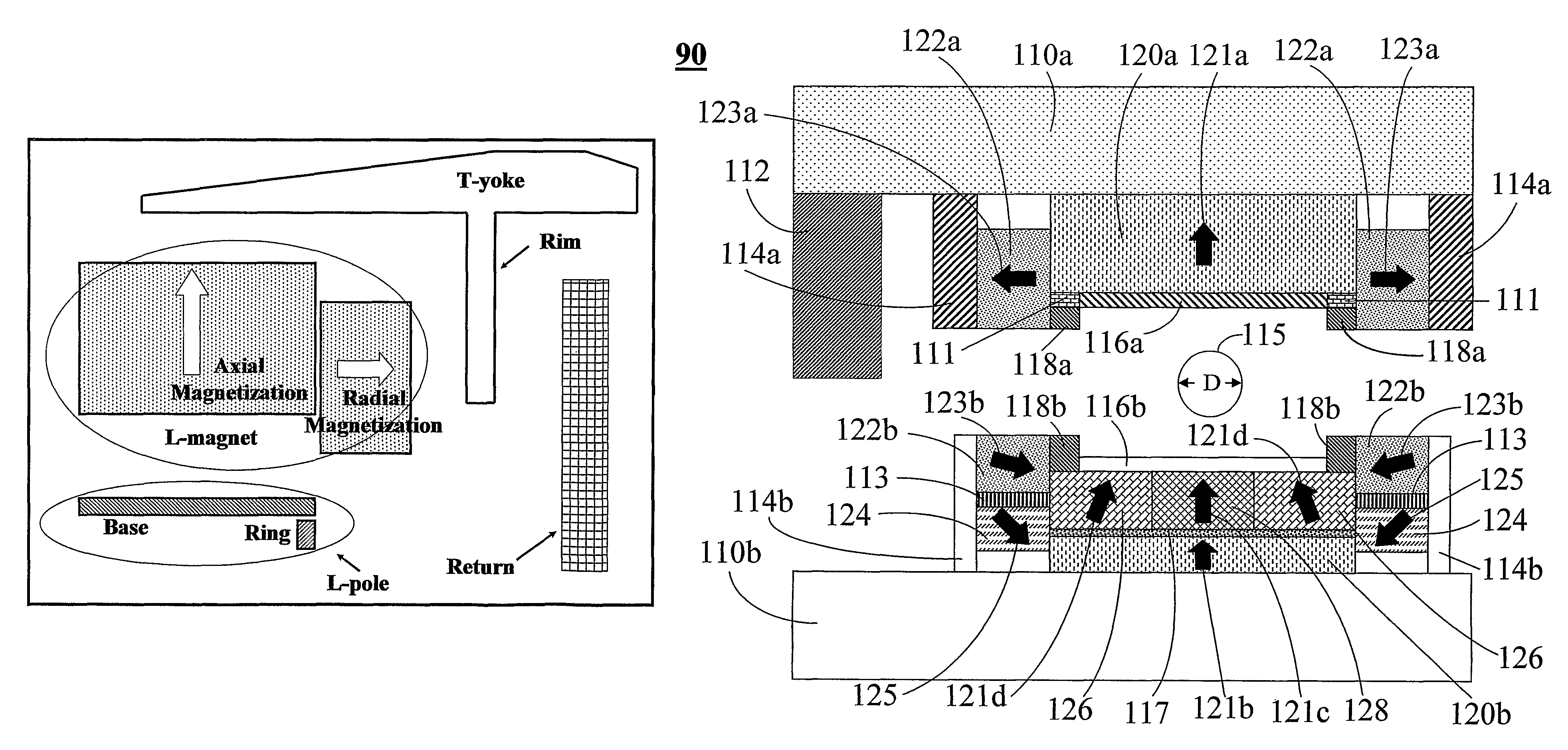
In Case 2, the ring magnet portions are all exhibiting a tilted magnetization orientation of 15° with respect to the horizontal, ρ-axis of FIG. 21. This is a very beneficial aspect of the invention as already mentioned previously adding about 100 G to the central field value and improving the homogeneity to about 500 ppm. A further enhancement upon this performance is changing the middle portions of the disk permanent magnets, 117a and 117b to a ferromagnetic material. As Case 3 shows, doing so adds about 30 G and has minimal impact on the central field value. However small this change is though the benefit from this part of the invention is for the assembly part of the magnet because the magnetic forces are significantly reduced if the disk magnets are split into at least two halves before insertion into the magnetic circuit. Furthermore, the flux lines are pulled back towards the returns away from the central portion of the magnet by making elements 117a and 117b a ferromagnetic m...

case 10

Case 10 is a check on the effect of just changing the magnetization orientation in the upper portion of the ring magnet 124. The result clearly shows that the central field value is increased by about 30 G without any effect on the homogeneity. Therefore, adjustments of this portion of the ring magnet give fine control over the central field value. Case 11 shows the benefits of changing the edge portion of the L-poles, 111 to a permanent magnet. It adds about 250 G to the central field value and significantly reduces the overall saturation of the L-poles. In contrast changing the Rose shims, 118, to permanent magnets, Case 12, has a similar effect as well and varying the magnetization orientation adjusts saturation of the L-poles and the overall homogeneity.

In more practical implementations of this magnet system a polygonal shape to the L-magnets and the L-poles is easier in which case the sections have to be at least 8 and preferably 32 or more for a better circumferential approxim...


PUM

PropertyMeasurementUnit
magnetic fieldaaaaaaaaaa
magnetic fieldsaaaaaaaaaa

Abstract

A magnet primarily for use in MRI applications comprises a pair of poles oriented about a plane of symmetry parallel to each therebetween defining an air gap region, magnetic field sources secured on the surfaces of the poles opposite the air gap that have yokes disposed on them, the yokes connected to each other by returns so that the entire magnet assembly can form a closed magnetic flux circuit to substantially confine the magnetic fields generated by the apparatus in the air gap where an imaging region is formed to place subjects for the purposes of examination. The main assembly being cylindrical in geometry has permanent magnets for magnetic field sources that are composed of two regions, a central disk-like portion magnetized substantially along the axial direction and an outer ring-like region magnetized substantially along the radial direction extending axially to form part of the pole together producing a very efficient and even flux distribution throughout the entire magnet assembly with minimal flux leakage. A further means of reducing flux leakage is incorporated in the yokes which have two sections, a disk-like region and an ring-like section to enclose the permanent magnets. The poles are made of multiple sections with a central disk-like region and an outer ring-like region that is a combination of permanent magnets and high permeability materials. This magnet assembly can achieve 1.0 Tesla or greater magnetic fields for whole-body scanning without saturating the magnet pole and other structures.

Description

BACKGROUND OF THE INVENTION1. Field of the InventionThe invention relates to a new class of permanent magnet designs that can generate very strong and highly homogeneous fields for NMR, MRI and MRT use. In particular, the magnet is capable of generating field strengths of 1.0 Tesla or greater and still accommodate whole-body imaging without saturating the pole piece and surrounding magnet structures.2. Description of the Related ArtIn MRI the strength of the NMR signal is proportional to the magnetic field and so the greater the magnetic field the stronger the NMR signal which translates into improved image quality and faster acquisition of image data. For whole-body imaging field strengths greater than 0.5 Tesla were only achieved using superconducting coils typically in cylindrical configurations although recently there have been 1.0 Tesla open configurations as well. However, magnets based on superconducting coil technology require dual cryogen systems and periodic refilling maki...

Claims


Application Information

Patent Timeline
Patent Type & Authority Patents(United States)
IPC IPC(8): H01F7/02
CPCG01R33/3806G01R33/383
Inventor LIAN, JIANYUTEKLEMARIAM, GRUMHU, XIAOPING
Owner LIAN JIANYU
Why Eureka
Try Eureka