Eureka AIR delivers breakthrough ideas for toughest innovation challenges, trusted by R&D personnel around the world.

Non-magnetic toner

a non-magnetic toner and a technology of toner, applied in the field of toner, to achieve the effect of excellent fixing ability and developing ability

Active Publication Date: 2011-12-27
CANON KK
View PDF31 Cites 14 Cited by
  • Summary
  • Abstract
  • Description
  • Claims
  • Application Information

AI Technical Summary

Benefits of technology

[0025]An object of the present invention is to provide a toner excellent in fixing ability and developing ability.
[0026]To be specific, an object of the present invention is to provide a toner which hardly causes the contamination of a charge-providing member, a regulating member, or a charging member for a photosensitive member even when a large number of sheets are continuously printed while good low-temperature fixing ability and high gloss are maintained even at a high speed and which provides an image having a stabilized image density and no fogging and excellent in durable stability.

Problems solved by technology

However, the reduction still involves problems to be alleviated in terms of specific image quality items, in particular, fogging at the time of durable printing, fusion to a photosensitive member, toner scattering, and the like.
A possible cause for the problems is a reduction in charge amount of toner due to the following two facts: the fact that an external additive added to a toner particle deteriorates owing to the long-term use of toner and the fact that a charge-providing member such as a sleeve or a carrier and a regulating member for keeping the coating property of toner on a sleeve at a predetermined value are contaminated by the toner or the external additive, that is, spent occurs.
In the case of the charge-providing member or the regulating member, such members may be contaminated by a toner component containing an external additive, or a coat component with which the charge-providing member is coated so that charging is properly stabilized may wear or be destroyed.
Furthermore, a photosensitive member or a charging member for the photosensitive member may be contaminated by an external additive liberated from the toner.
As the number of printing increases, those damages preclude the maintenance of the initial properties of a developer, and become causes of fogging, contamination in a machine, and fluctuation in image density.
On the other hand, the release agent reduces the blocking resistance of toner or reduces the developing ability of the toner owing to a temperature increase in a developing device.
However, problems still remain regarding how to provide developing ability that is stable for a long time period upon temperature increase in a developing device due to continuous paper transport while maintaining good fixing ability.[Patent Document 1] JP 3-50559 A[Patent Document 2] JP 2-79860 A[Patent Document 3] JP 1-109359 A[Patent Document 4] JP 6-59502 A[Patent Document 5] JP 8-54750 A[Patent Document 6] JP 9-34163 A[Patent Document 7] JP 2002-13196 A[Patent Document 8] JP 2004-333968 A[Patent Document 9] JP 2004-151638 A[Patent Document 10] JP 2004-157342 A[Patent Document 11] JP 2004-264484 A

Method used


Image

  • Non-magnetic toner
  • Non-magnetic toner
  • Non-magnetic toner

Examples


production example 6

of Toner

[0166]A toner (F) was obtained in the same manner as in except that the amount of the 70% solution of the polymerization initiator 1,1,3,3-tetramethylbutylperoxy-2-ethylhexanoate in toluene was changed to 12 parts by mass.

production example 7

of Toner

[0167]A toner (G) was obtained in the same manner as in except that: the amount of divinylbenzene to be added was changed to 0.05 part by mass; and the temperature at which stirring was performed by using a paddle stirring blade after granulation was changed to 65° C.

production example 8

of Toner

[0168]A toner (H) was obtained in the same manner as in except that: no hydrocarbon-based wax was added; and 9 parts by mass of an ester wax (behenyl behenate: maximum heat absorption peak=75° C., Mw=700) were added.


PUM


Abstract

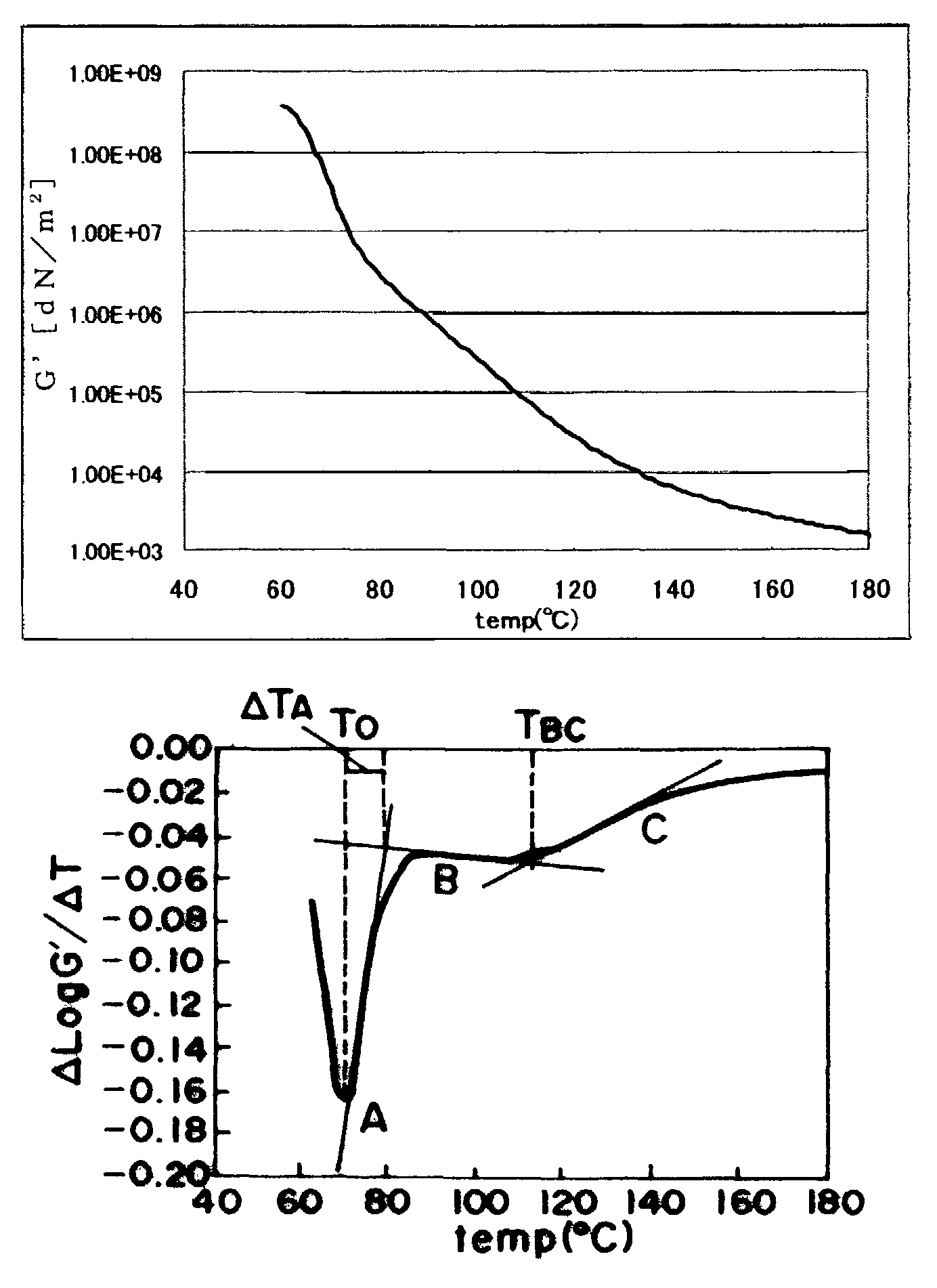
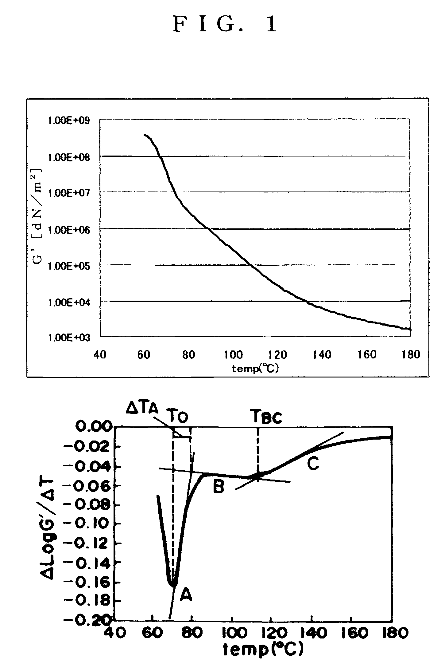
A non magnetic toner comprises toner particles each containing at least a binder resin, a colorant and a wax component. The toner further comprises an inorganic fine powder. A storage elastic modulus at 110° C. (G′110) of the non magnetic toner is in a range of 2.00×10⁴ to 2.00×10⁵ dN / m2. A storage elastic modulus at 150° C. (G′150) of the non magnetic toner is in a range of 3.00×10³ to 2.00×10⁴ dN / m2. The toner particles are obtained by dispersing a polymerizable monomer composition containing polymerizable monomers, the colorant, the wax component and a low-molecular weight polymer into an aqueous medium, granulating the dispersed polymerizable monomer composition, and polymerizing the polymerizable monomers in granulated particles. The low-molecular weight polymer has a weight average molecular weight (Mw) measured by means of gel permeation chromatography (GPC) in a range of 2000 to 5000.

Description

TECHNICAL FIELD[0001]This application claims priority from Japanese Patent Application No. 2006-001074 filed on Jan. 6, 2006 and Japanese Patent Application No. 2006-060682 filed on Mar. 7, 2006, which are hereby incorporated by reference herein.[0002]The present invention relates to a toner for use in a recording method utilizing an electrophotographic method, an electrostatic recording method, a magnetic recording method, a toner jet method, or the like.BACKGROUND ART[0003]A large number of electrophotographic methods have been conventionally known. A general electrophotographic method involves: utilizing a photoconductive substance; forming an electrostatic latent image on a photosensitive member by using various means; developing the latent image with toner to provide a visible image; transferring the toner onto a recording material (transfer material) such as paper as required; and fixing the toner image to the recording material by using heat or pressure to provide a copied ar...

Claims


Application Information

Patent Timeline
Patent Type & Authority Patents(United States)
IPC IPC(8): G03G9/087
CPCG03G9/0806G03G9/0819G03G9/0821G03G9/08711G03G9/08726G03G9/08728G03G9/08755G03G9/08782G03G9/08795G03G9/08797G03G9/09708
Inventor TOSAKA, EMIABE, KOJIMIKURIYA, YUSHIHANDA, SATOSHIYACHI, SHINYAYOSHIZAKI, KAZUMIHASHIMOTO, YASUHIRO
Owner CANON KK
Why Eureka
Eureka Blog
Learn More