Apparatus and method for broadband amplifier linearization

a broadband amplifier and linearization technology, applied in the field of electrical circuits, can solve the problems of reducing the effective amount of content or information that can be transmitted, reducing the ber (bit error rate), and reducing so as to improve the 3rd order distortion of the amplifier, improve the linearization effect of broadband, and reduce the amount of dc power required

Active Publication Date: 2012-01-24
QORVO US INC
View PDF10 Cites 10 Cited by
  • Summary
  • Abstract
  • Description
  • Claims
  • Application Information

AI Technical Summary

Benefits of technology

[0027]In general, the present invention is an apparatus and method to improve broadband linearization. The present invention makes use of pre-distortion techniques to improve the 3rd order distortion of an amplifier to reduce the amount of DC power required to achieve a given system requirement. In addition, the amplifiers have broadband characteristics which lend themselves to simplified pre-distortion.

Problems solved by technology

Amplifiers which add excessive distortion cause degradation of picture quality and reduced BER (bit error rate).
Each type of distortion leads to unique system impairments that limit the effective amount of content or information that can be transmitted through the system.
For example, 3rd order distortion in an amplifier causes QAM signals to develop spectral content which can impair the BER on the adjacent QAM channel.
Second order distortion impacts a CATV system is a number of ways, such as analog video picture quality.
Increasingly, in new CATV architectures, however, the presence of 2nd order distortion is a concern when both analog channels and QAM content are transmitted at the same time through an amplifier.
Since the original QAM content in the upper frequency is un-correlated to the analog content and therefore noise-like, the 2nd order distortion will manifest as an increase in the noise floor of the analog signal, thereby degrading picture quality.
The issue is heightened by the fact that newer CATV architectures strive to reduce the number of system amplifiers by outputting higher levels of RF signal with higher levels of tilt.
This further exasperates the 2nd order distortion issue and leads to significant design challenges in the design of CATV amplifiers.
In particular, high QAM levels must not be allowed to cause lower analog channels to have carrier-to-noise (CNR) issues.
Considering the newer QAM content and higher RF outputs, it's apparent many of the prior art linearization techniques did not did not address this issue with sufficient care.
While this readily drops the distortion, it also leads to higher power consumption since the larger transistors require more power to operate.
Often these newer transistor technologies pose significant reliability risks as they reach technical maturity.
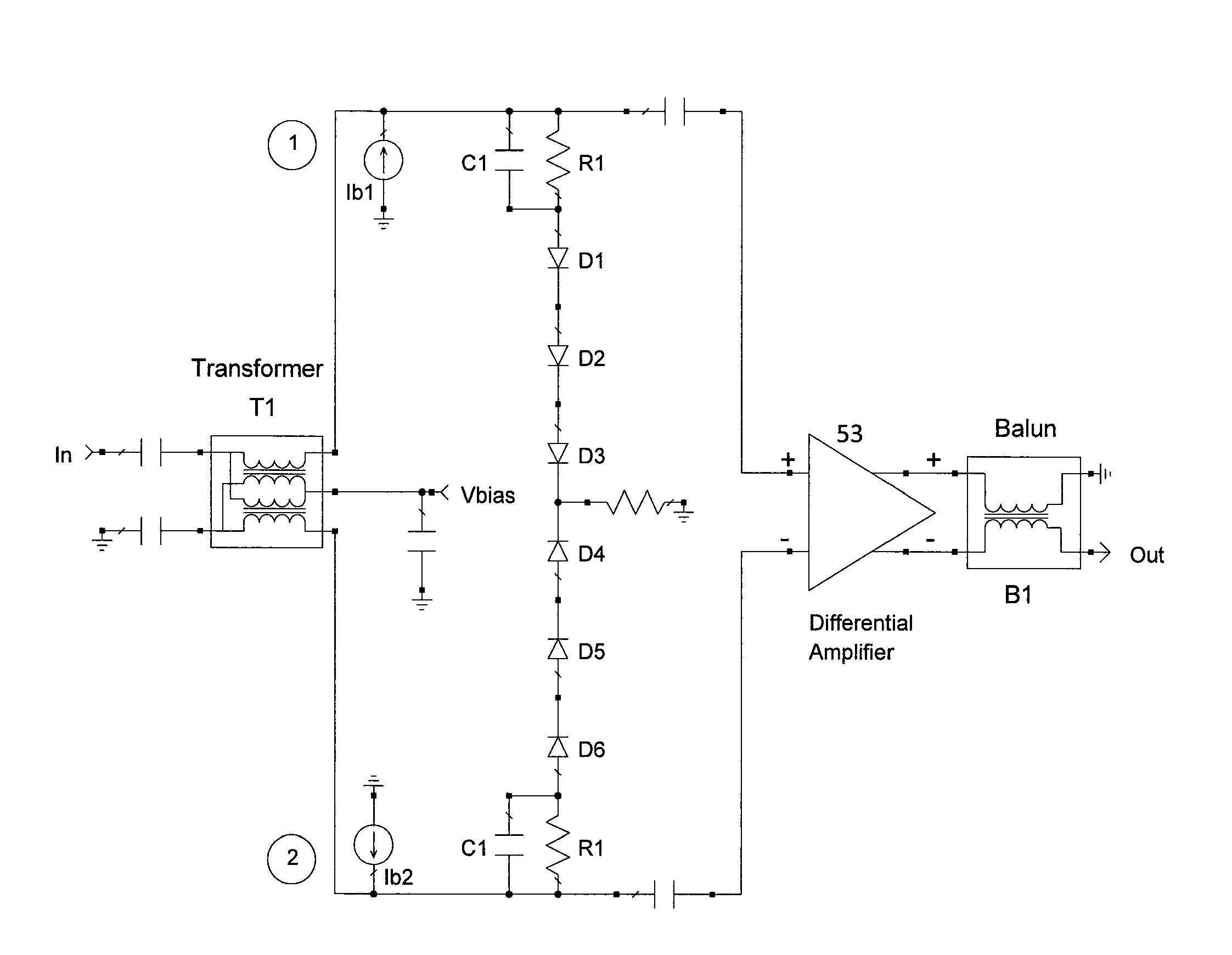
Hence, operation of the circuit in FIG. 1 can be thought of as a destructive interference circuit, where the goal is to achieve good alignment of both the magnitude and phases of the two distortion signals so there is as much cancellation as possible.
However, at higher frequencies, these capacitances can dominate amplifier distortion.
However, it tends to have poor performance because device capacitances can dominate the frequency response and high frequency distortion.
Even still, the 
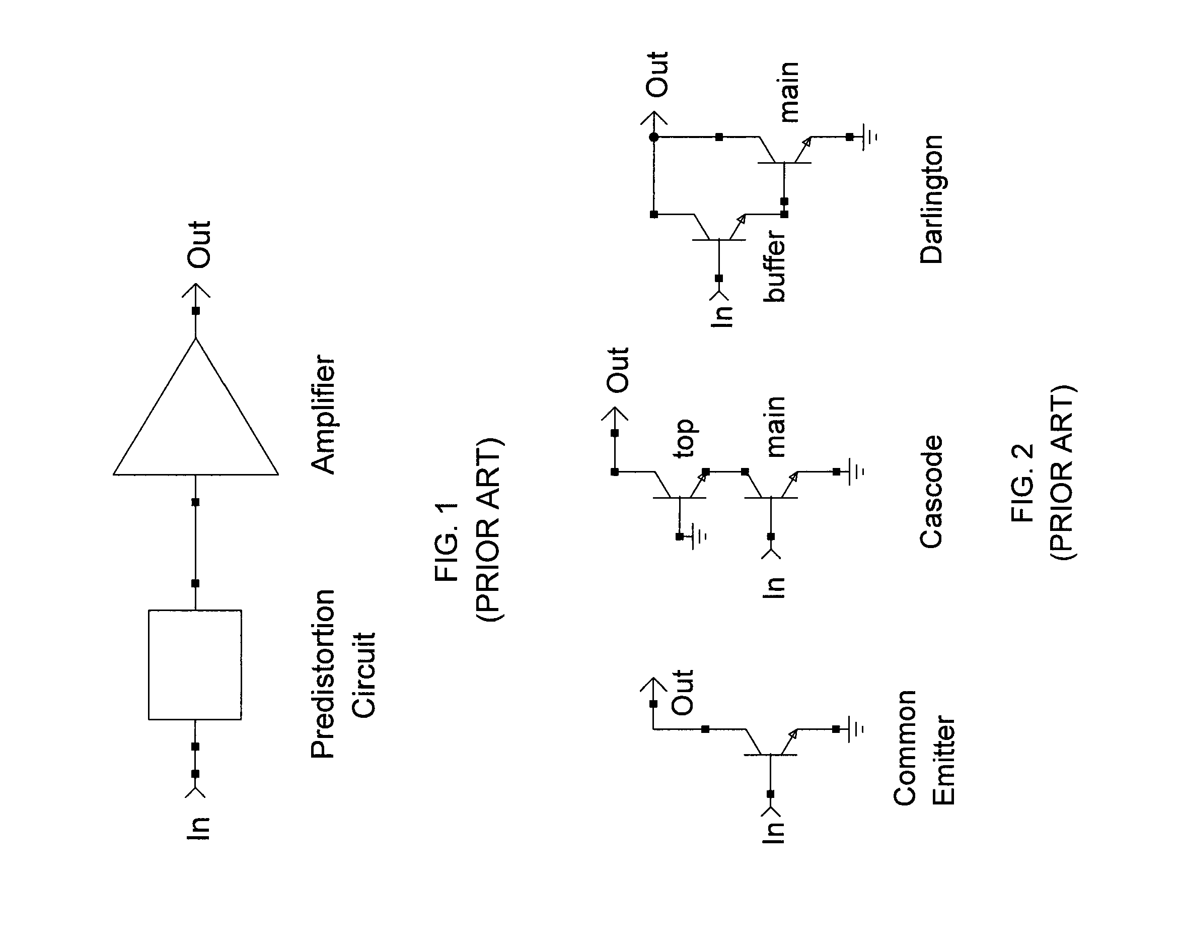
Cascode amplifiers used with older silicon technology still have significant degradation in their distortion performance as frequency increases.
Note the Darlington shown in FIG. 2 still suffers from the Miller effect and likewise has significant degradation in distortion performance at higher frequencies.
All amplifier topologies in FIG. 2 will have some degradation in distortion performance as frequency is increased.
This change in magnitude and phase of the distortion signal as frequency is increased makes the design of the linearizer much more difficult.
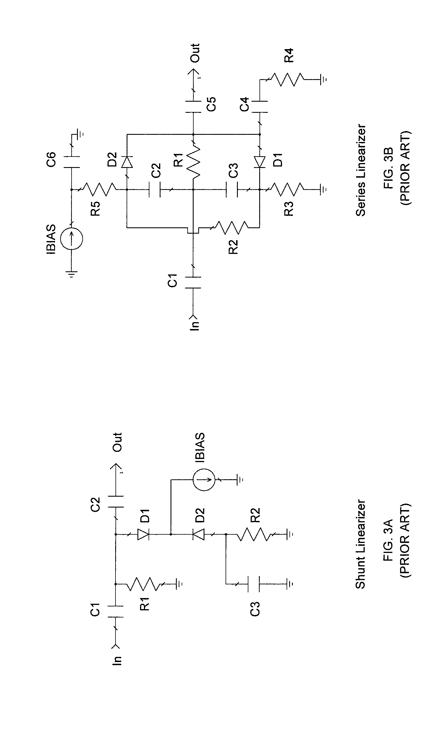
However, the forward bias current in D2 decreases, which causes its video resistance to increase.
This means the loss in the linearizer circuit decreases as the RF voltage increases.
However, the circuits disclosed in Miguelez and Cummings are not easily implemented in an integrated circuit because they require capacitors of large value to achieve the low frequency response needed.
The added capacitors will tend to reduce the possible benefits of integration due to their added parasitic length to the circuit.
In short, the series-type linearizers of Miguelez and Cummings do not lend themselves to integration.
A few prior art references that illustrate this are U.S. Pat. No. 5,589,797 (Gans, et al) and U.S. Pat. No. 5,436,749 (Pidgeon, et al), which both utilize delay lines and are hence not suitable for integrated circuit implementation.
However, the circuitry disclosed in Nazarathy is not well designed with respect to their suitability in an integrated circuit process with uncertain matching characteristics.
Any imbalance in the diode characteristics will lead to imbalance of currents in the diode branches and potentially large 2nd order distortion.
The potential for large 2nd order distortion makes Nazarathy of questionable value for integrated designs.
Furthermore, Nazarathy does not disclose the critical step of aligning the phase responses between the pre-distortion generator and amplifier, which as earlier noted can require large delay lines and greatly complicate the task of integration.
One problem with the pre-distortion circuit in FIG. 3A is the premature clipping of the linearizer before the amplifier compresses completely.
In other words, distortion characteristics from common linearizers, such as that in FIG. 3A, vary considerably as the input RF level is increased, and high amounts of RF drive can cause the linearizer to clip prematurely before the amplifier does.
This leads to very undesirable degradation of combined compression performance.
Very often in prior art linearizers the pre-distortion circuit adversely affects the high power performance of the combined response.

Method used


Image

  • Apparatus and method for broadband amplifier linearization
  • Apparatus and method for broadband amplifier linearization
  • Apparatus and method for broadband amplifier linearization

Examples


Embodiment Construction

[0053]The following description is provided to enable any person skilled in the art to make and use the invention and sets forth the best modes contemplated by the inventor for carrying out the invention. Various modifications, however, will remain readily apparent to those skilled in the art. Any and all such modifications, equivalents and alternatives are intended to fall within the spirit and scope of the present invention.

[0054]The present invention discloses how improved distortion can be achieved without adding extra power to the amplifier and without requiring that newer transistor technologies be used. The invention may be advantageously applied to a new CATV amplifier integrated circuit which achieves critical system distortion requirements while reducing power consumption by more than 40% compared with the current state of the art alternatives.

[0055]More particularly, the present invention makes use of pre-distortion techniques to improve the 3rd order distortion of a CATV...


PUM


Abstract

An apparatus and method to improve broadband amplifier linearization. The present circuits make use of pre-distortion techniques to improve the 3rd order distortion of an amplifier to reduce the amount of DC power required to achieve a given system requirement. In addition, the amplifiers have broadband characteristics which lend themselves to simplified pre-distortion. A pre-distortion linearizer circuit is connected across the input terminals of an amplifier. The linearizer circuit includes multiple diodes to improve the clipping performance of the linearizer. In addition, RC circuits align the phase of the linearizer distortion to be opposite that of the amplifier.

Description

[0001]This application claims priority to U.S. Provisional Patent Application Ser. No. 61 / 106,455, entitled BROADBAND AMPLIFIER LINEARIZATION, filed Oct. 17, 2008, the disclosure of which is herein incorporated.BACKGROUND OF THE INVENTION[0002]1. Field of the Invention[0003]The present invention relates generally to electrical circuits, and more particularly, to circuits and techniques for broadband amplifier linearization.[0004]2. Description of the Related Art[0005]Efficient transmission of broadband information such as analog CATV and digital QAM (quadrature amplitude modulation) signals requires linear amplification of content throughout networks. Linear amplifiers are those which add low amounts of distortion as they increase the amplitude of a signal. Amplifiers which add excessive distortion cause degradation of picture quality and reduced BER (bit error rate). Maintaining good distortion performance throughout the system requires careful attention to the design of amplifiers...

Claims


Application Information

Patent Timeline
Patent Type & Authority Patents(United States)
IPC IPC(8): H03F3/26
CPCH03F1/3211H03F3/45188H03F3/45475H03F2203/45568H03F2200/534H03F2200/541
Inventor DAY, CHRIS J.
Owner QORVO US INC
Why Eureka
Try Eureka