Suspension system for vehicle

a suspension system and vehicle technology, applied in the direction of cycle equipment, transportation and packaging, instruments, etc., can solve the problems of not being able to deal with vibration with the coupled motion, the disclosed suspension apparatus does not consider the coupled motion of the vehicle, and the disclosed suspension apparatus fails to offer a vibration suppressing or restraining

Active Publication Date: 2012-01-24
KYB CORP +2
View PDF20 Cites 10 Cited by
  • Summary
  • Abstract
  • Description
  • Claims
  • Application Information

AI Technical Summary

Benefits of technology

[0024]In the form (6), the structure of the coil connecting device is limited in an instance where the four electromagnetic absorbers are connected. Like the above form, the form (6) ensures a simplified structure of the coil connecting device.
[0072]According to the form (33), even when the voltage of the power source is somewhat lowered due to a decrease in the electric energy charged in the power source such as a battery, it is possible to effectively reduce or avoid an adverse influence due to a further decrease in the voltage resulting from a continued execution of the active control, e.g., an adverse influence that is given to the other system.

Problems solved by technology

Therefore, the disclosed apparatus lacks in consideration of a coupled motion of the vehicle.
Accordingly, the disclosed suspension apparatus fails to offer a vibration suppressing or restraining effect that is provided by a cooperative action of two electromagnetic absorbers respectively provided for left and right wheels of the vehicle, for instance.
On the other hand, in the electromagnetic suspension apparatus disclosed in the above-indicated Publication JP-A-2001-310736, while it is possible to deal with the coupled motion in which a left-side motion and a right-side motion are coupled, by connecting the two coils provided for the left and right wheels, it is not possible to deal with a vibration with the coupled motion in which a front-side motion and a rear-side motion are coupled.
The above-described problems are just a part of problems experienced in the system having the electromagnetic suspension apparatus, namely, the electromagnetic suspension system.
Since the electromagnetic suspension system is still under development, the system suffers from various other problems including those described above.

Method used


Image

  • Suspension system for vehicle
  • Suspension system for vehicle
  • Suspension system for vehicle

Examples


first embodiment

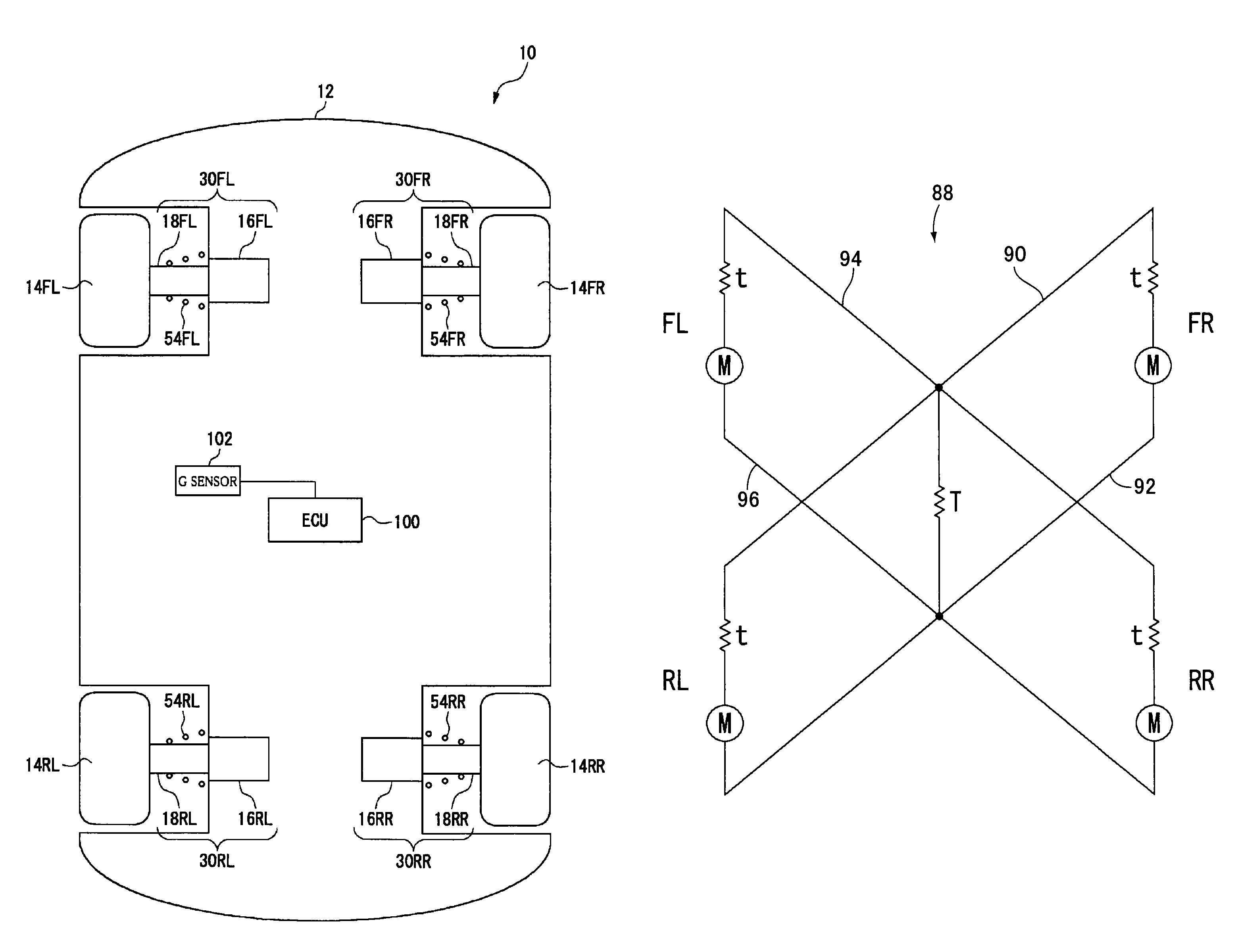
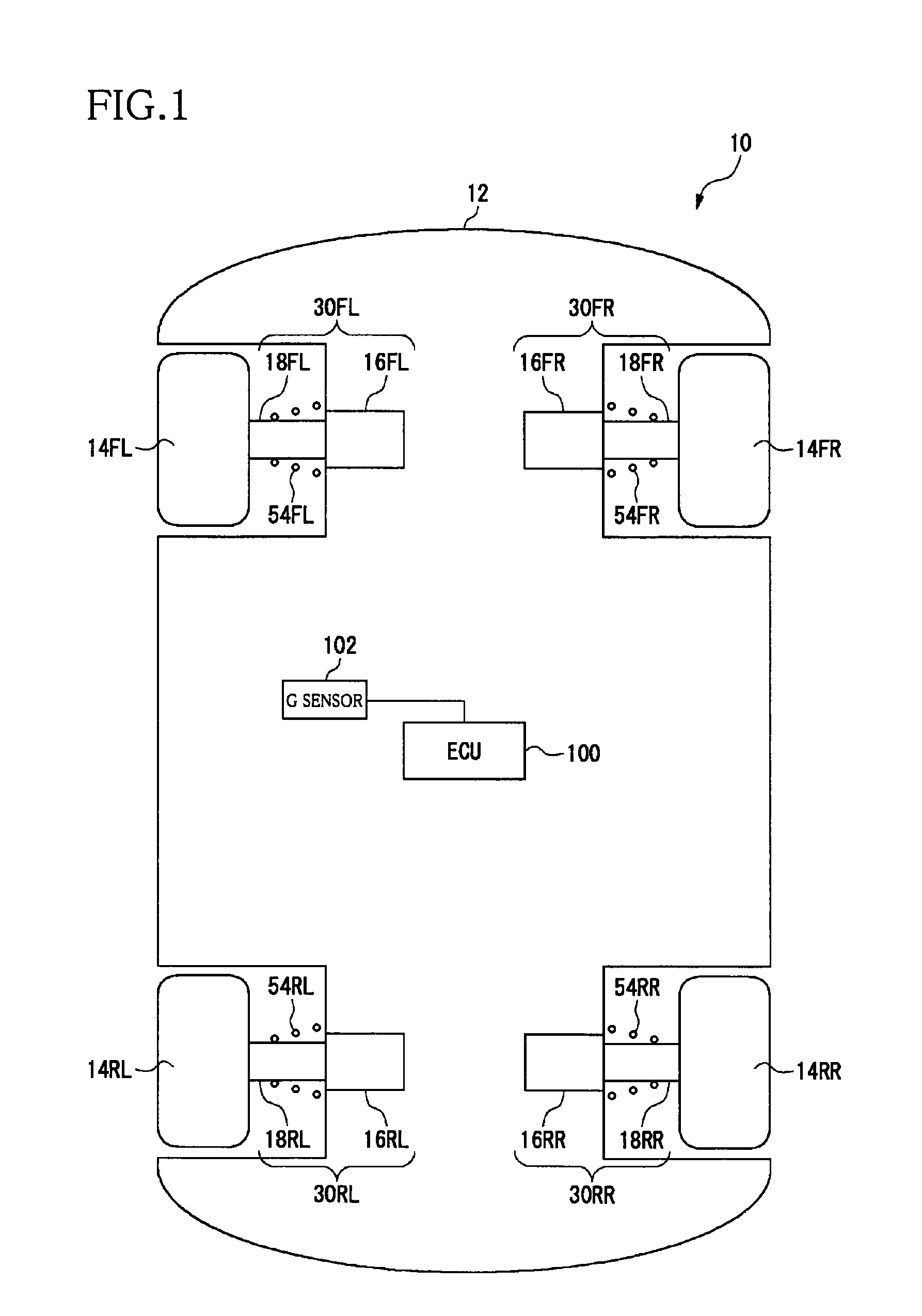
[0097]FIG. 1 is a schematic view of a vehicle 10 equipped with a suspension system according to a first embodiment. Between a body 12 of the vehicle 10 and the wheels 14FR, 14FL, 14RR, 14RL, there are respectively disposed coil springs 54FR, 54FL, 54RR, 54RL each as a suspension spring and electromagnetic absorbers 30FR, 30FL, 30RR, 30RL. In the respective electromagnetic absorbers 30FR, 30FL, 30RR, 30RL, motors 16FR, 16FL, 16RR, 16RL each functioning as a generator and cylinder devices 18FR, 18FL, 18RR, 18RL each functioning as a telescopic member are disposed in series. In the following description, the wheels, the coil springs, the motors, the cylinder devices, and the electromagnetic absorbers may be collectively referred to as “wheel(s) 14”, “coil spring(s) 54”, “motor(s) 16”, “cylinder device(s) 18”, and “electromagnetic absorber(s) 30”, respectively, where appropriate. It is noted that the reference numerals “FR”, “FL”, “RR”, and “RL” respectively indicate a front right posit...

second embodiment

[0132]In a vehicle suspension system according to a second embodiment, it is possible to selectively establish a state in which one electromagnetic absorber alone can generate a damping force and a state in which an appropriate vibration suppressing action can be exhibited with respect to the vibration with the coupled motion, by connecting the coil of the above-indicated one electromagnetic absorber and the coil of any of the other three electromagnetic absorbers.

[0133]FIG. 6 is a schematic view of a vehicle 10 equipped with the suspension system according to the second embodiment. The wheels 14, the electromagnetic absorbers 30 each including the motor 16 and the cylinder device 18, the G sensor 102 and so on, are identical in construction with the corresponding components in the illustrated first embodiment, and a detailed description of which is dispensed with by using the same reference numerals as used in the first embodiment.

[0134]In the present suspension system, the electro...

third embodiment

[0150]In a suspension system according to a third embodiment, a control mode of each of the four electromagnetic absorbers is selectively changeable between: a control (so-called “passive control”) in which the damping force is generated mainly by utilizing the electromotive force generated by the motor 16; and a control (so-called “active control”) that allows the above-indicated power-reception operation in which the damping force or the impulsive force is generated by supplying the electric power from the power source to the motor 16.

[0151]FIG. 12 is a schematic view of a vehicle 10 equipped with the suspension system according to the third embodiment. The wheels 14, the electromagnetic absorbers 30 each including the motor 16 and the cylinder device 18, the G sensor 102, the stroke sensors 112 and so on, are identical in construction with the corresponding components in the illustrated first or second embodiment, and a detailed description of which is dispensed with by using the...


PUM


Abstract

In a system including four electromagnetic absorbers for respective four vehicle wheels, motor coils of two respective electromagnetic absorbers disposed corresponding to two diagonally located wheels are connected forming a closed loop including the coils. A generated damping force magnitude can be made different between an instance directions of respective movements of the diagonally located two wheels with respect to the vehicle body are the same, and an instance the directions are opposite each other. Each electromagnetic absorber includes a resistor cooperating with the corresponding coil forming a closed loop, and selectively establishes: a connected state in which one of the four coils and any of the other three coils are connected to form a closed loop; and a non-connected state in which the one of the four coils is not connected to any other coil. An appropriate vibration suppressing action is exhibited with respect to a coupled motion.

Description

TECHNICAL FIELD[0001]The present invention relates to a suspension system for a vehicle and more particularly to such a suspension system equipped with electromagnetic absorbers.BACKGROUND ART[0002]A suspension apparatus for an automotive vehicle not only supports a weight of the vehicle (a sprung weight), but also mitigates vibrations due to roughness of a road surface for improving ride comfort of the vehicle and reduces dynamic load that is applied to various portions of a body of the vehicle for improving running stability of the vehicle. One of elements that constitute the suspension apparatus is a shock absorber, and there has been developed, as the shock absorber, an electromagnetic absorber operable to generate, based on a force of a motor, a damping force with respect to a relative movement of a sprung portion and an unsprung portion of the vehicle.[0003]The above-described electromagnetic absorber is operable to generate the damping force by shortcircuiting a coil of the m...

Claims


Application Information

Patent Timeline
Patent Type & Authority Patents(United States)
IPC IPC(8): B60G17/015
CPCB60G17/06F16F15/03B60G2202/42B60G2400/102B60G2400/104B60G2400/106B60G2400/204B60G2400/252B60G2400/41B60G2500/10B60G2800/012B60G2800/014
Inventor INOUE, HIROFUMIKONDO, TAKUHIROSUDA, YOSHIHIRO
Owner KYB CORP
Why Eureka
Try Eureka