Multiprocessor system and method of synchronization for multiprocessor system

a multi-processor system and multi-processor technology, applied in the field of multi-processor system and a method of synchronization of the same, can solve the problems of time consumption, process may consume time, and it is difficult to carry out so as to achieve high-speed barrier synchronization processing, speed can be increased, and the effect of barrier synchronization processing

Active Publication Date: 2012-01-31
WASEDA UNIV +1
View PDF18 Cites 5 Cited by
  • Summary
  • Abstract
  • Description
  • Claims
  • Application Information

AI Technical Summary

Benefits of technology

[0014]When such a configuration is used, the first information can be promptly reflected to the barrier read register(s) of the other processor(s) when a certain processor writes the first information, which indicates that the processor is waiting for own synchronization, to the barrier write register of its own. Therefore, each of the other processor(s) is capable of promptly understanding whether the processor(s) other than itself is waiting for synchronization or not by reading the barrier read register of its own; therefore, high-speed barrier synchronization processing can be realized. In this process, the speed can be increased when the information transmission from the barrier write register to the barrier read register is carried out by using a dedicated wiring block without the intermediation of a system bus.
[0015]In addition, the processor is supposed to write the first information to the barrier write register of its own for notifying that the processor is waiting for synchronization to the other processor(s), and the processor is supposed to read the barrier read register of its own for understanding the synchronization stand-by state of the other processor(s); therefore, special instruction sets are not required to be added to the CPUs, and barrier synchronization processing can be realized at low cost. Furthermore, when the processor(s) other than its own writes the first information to the barrier write register, the first information is configured to be directly reflected to the barrier read register in the processor itself instead of an indirect mode such as interruption; therefore, the process currently carried out by the processor itself is not disturbed along with the reflection. Thus, a highly-efficient barrier synchronization processing can be realized.
[0017]Furthermore, in the multiprocessor system of an embodiment of the present invention, the abovedescribed barrier write register has a plurality of bits. Consequently, a plurality of types of synchronization points can be set as version numbers, thereby flexibly handling advanced or complex barrier synchronization processing. For example, each layer of abovedescribed plurality of layers can be allocated to each bit of the plurality of bits of the barrier write register. When a plurality of sets of the barrier write registers and barrier read registers are provided as described above, and, in addition, when the abovedescribed version numbers are used in combination, further advanced or complex barrier synchronization processing can be flexibly handled.
[0019]When a multiprocessor system according to an embodiment of the present invention is used, highly-efficient barrier synchronization processing can be realized.

Problems solved by technology

However, in the methods by software, time is consumed to complete the barrier synchronization since the processors access the shared flag variables in the shared memory.
In this case, since the access to the flag register has to be exclusively controlled, this process may consume time.
However, when the system bus is used, arbitration time for ensuring the right to access the bus is required; therefore, it becomes difficult to carry out high-speed barrier synchronization processing.

Method used


Image

  • Multiprocessor system and method of synchronization for multiprocessor system
  • Multiprocessor system and method of synchronization for multiprocessor system
  • Multiprocessor system and method of synchronization for multiprocessor system

Examples


first embodiment

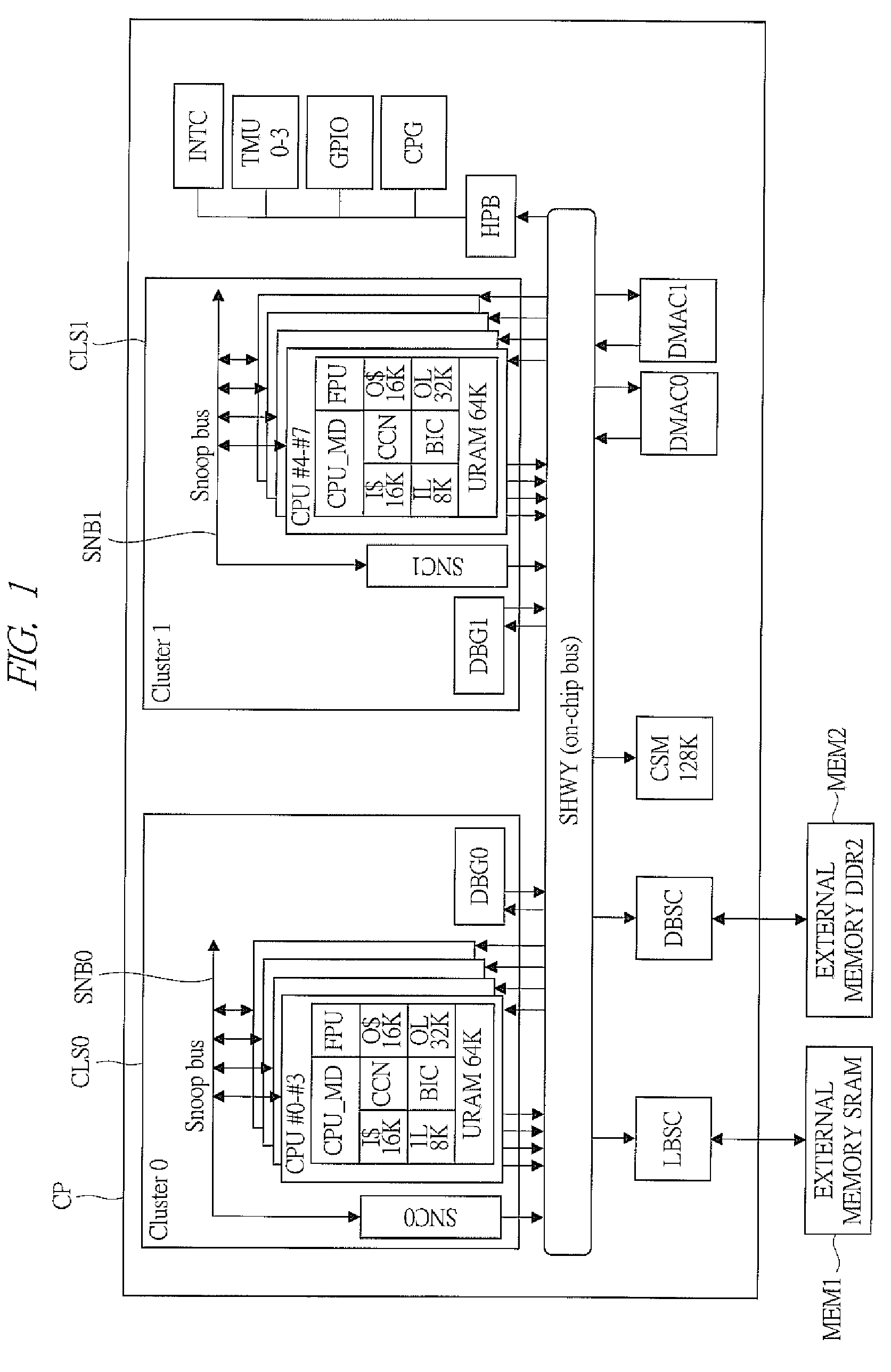
[0044]FIG. 1 is a block diagram showing an example of an entire configuration of a multiprocessor system according to a first embodiment of the present invention. The multiprocessor system shown in FIG. 1 has, for example, a semiconductor chip CP including processors, etc., an external memory MEM1 such as an SRAM (Static Random Access Memory), and an external memory MEM2 such as a DDR2-SDRAM (Double Data Rate 2 Synchronous Dynamic Random Access Memory). The semiconductor chip CP is, though not particularly limited to this, formed on a semiconductor substrate of, for example, silicon, by a publicly-known CMOS fabrication method.

[0045]The semiconductor chip CP contains, though not particularly limited to this, a system bus SHWY. To the SHWY, a plurality of (herein, two) clusters CLS0 and CLS1, memory controllers LBSC and DBSC, a shared memory CSM, DMA (Direct Memory Access) controllers DMAC0 and DMAC1, a peripheral bus bridge HPB, etc. are connected. On the other side of HPB, a clock ...

second embodiment

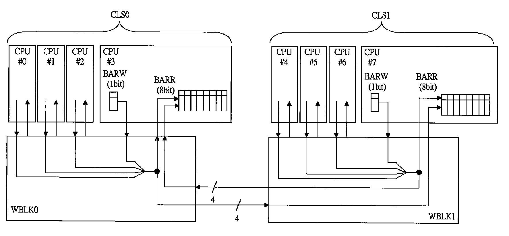
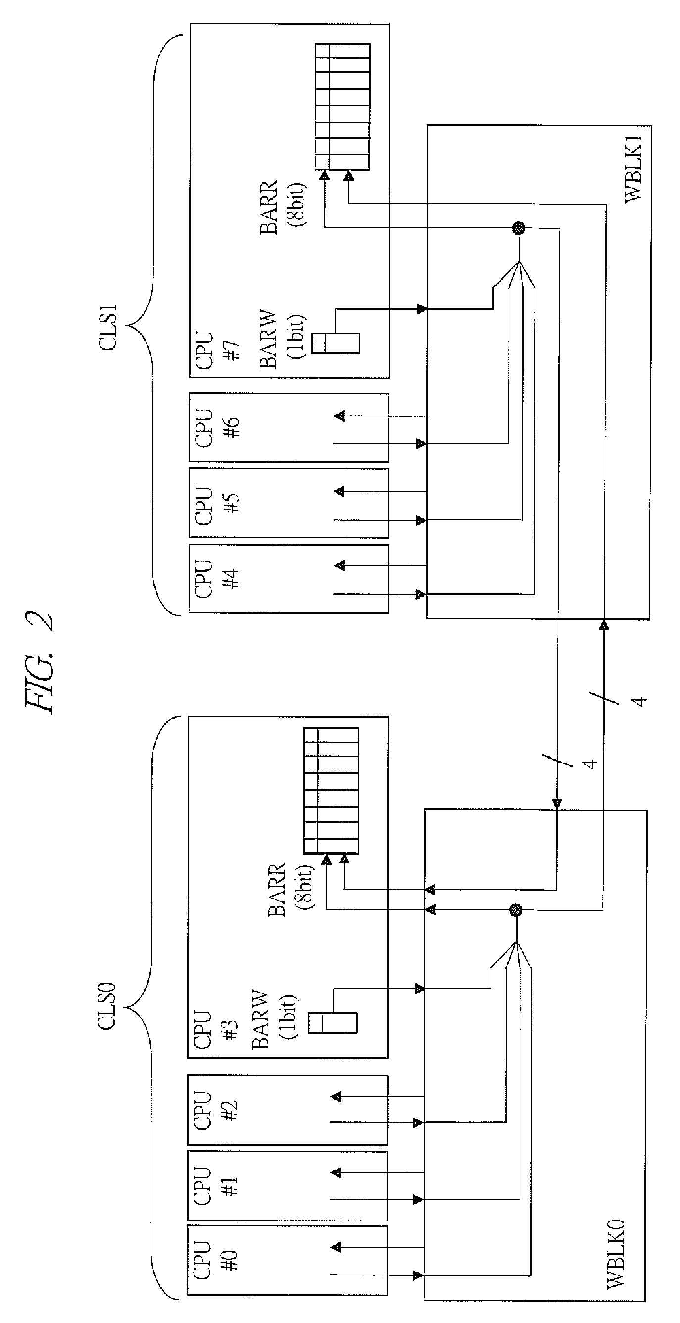
[0068]FIG. 7 is a schematic diagram showing a configuration example of a main part of a multiprocessor system according to a second embodiment of the present invention. In the abovedescribed first embodiment, the configuration example in which the barrier write register BARW and the barrier read register BARR are different registers (in the case of the address mapped register, a register in which addresses are individually allocated) has been shown. On the other hand, the multiprocessor system shown in FIG. 7 has a feature that the barrier write register BARW and the barrier read register BARR in abovedescribed FIG. 3 are integrated and serve as a common barrier register BAR. In FIG. 7, each of a plurality (herein, eight) of processors CPU#0 to CPU#7 has an 8-bit barrier register BAR. The equivalent bits in the barrier registers BAR are mutually connected by direct wiring by a wiring block WBLK5. More specifically, for example, eight bits [0] of BAR contained in the CPUs CPU#0 to CP...

third embodiment

[0071]FIG. 8 is a schematic diagram showing a configuration example of a main part of a multiprocessor system of a third embodiment of the present invention. The multiprocessor system shown in FIG. 8 has a feature that one of the plurality of processors CPUs (herein, CPU CPU#0) serves as a master and that the master proactively monitor the synchronization stand-by state of the other CPUs, thereby reducing the number of bits of the barrier read register BARR compared with the abovedescribed case of FIG. 3.

[0072]In FIG. 8, the CPU CPU#0 serving as the master has the 1-bit barrier write register BARW and a 7-bit (herein, in order to facilitate understanding of the correspondence relation, the bit [0] is omitted, and the bits [1] to [7] are provided) barrier read register BARR. On the other hand, each of the other CPUs CPU#1 to CPU#7 has the 1-bit barrier write register BARW and a 1-bit barrier read register BARR. In a wiring block WBLK6, the bits of the 7-bit BARR in the CPU CPU#0 and ...


PUM


Abstract

Each of processors has a barrier write register and a barrier read register. Each barrier write register is wired to each barrier read register by a dedicated wiring block. For example, a 1-bit barrier write register of a processor is connected, via the wiring block, to a first bit of each 8-bit barrier read register contained in the processors, and a 1-bit barrier write register of another processor is connected, via a wiring block, to a second bit of each 8-bit barrier read register contained in the processors. For example, a processor writes information to its own barrier write register, thereby notifying synchronization stand-by to the other processors and reads its own barrier read register, thereby recognizing whether the other processors are in synchronization stand-by or not. Therefore, a special dedicated instruction is not required along barrier synchronization processing, and the processing can be made at a high speed.

Description

CROSS-REFERENCE TO RELATED APPLICATION[0001]The present application claims priority from Japanese Patent Application No. JP 2008-015028 filed on Jan. 25, 2008, the content of which is hereby incorporated by reference into this application.TECHNICAL FIELD OF THE INVENTION[0002]The present invention relates to a multiprocessor system and a method of synchronization of the same. More particularly, the present invention relates to a technique effectively applied to a multiprocessor system that carries out barrier synchronization processing by hardware and a method of synchronization for the same.BACKGROUND OF THE INVENTION[0003]For example, Japanese Patent Application Laid-Open Publication No. H02-105961 (Patent Document 1) describes a method of carrying out synchronization between processors in a multiprocessor system having “N” number of processors connected to a system bus, which is provided with a broadcasting function, via a bus interface. Specifically, each of the processors has a...

Claims


Application Information

Patent Timeline
Patent Type & Authority Patents(United States)
IPC IPC(8): G06F1/04
CPCG06F15/16
Inventor KASAHARA, HIRONORIKIMURA, KEIJIITO, MASAYUKIKAMEI, TATSUYAHATTORI, TOSHIHIRO
Owner WASEDA UNIV
Why Eureka
Try Eureka