Optical transmitting and receiving system

a technology applied in the field of optical transmission and receiving system, can solve the problems of general difficulty in performing psk or dpsk using anti-squeezed light, signal processing speed cannot be increased, signal processing becomes complex, etc., and achieves the effect of simple processing

Inactive Publication Date: 2012-02-21
HITACHI LTD
View PDF7 Cites 0 Cited by
  • Summary
  • Abstract
  • Description
  • Claims
  • Application Information

AI Technical Summary

Benefits of technology

[0008]An object of the present invention is therefore to increase the signal processing speed and simplify signal processing to be as simple as that in ordinary optical communications even in a method in which two optical pulses originating in the same light source are transmitted for interference.
[0009]In general, it is easier to achieve an increase in speed in an optical domain than to increase the speed of an electric circuit. Although use of an asymmetric interferometer increases the total number of optical pulses, the present invention provides means for maintaining the clock of an electric circuit.
[0012]According to the present invention, high-speed, simple processing is achieved in a method in which signals are superimposed on optical phase even when low-coherency light, such as antisqueezed light, is used. The present invention thus allows not only optical communications based on quantum mechanics, but also, not limited thereto, optical communications using phase modulation even when low-coherency light is used.

Problems solved by technology

Therefore, it is generally difficult to perform PSK or DPSK using antisqueezed light.
Therefore, the signal processing speed cannot be increased, and signal processing becomes complex.

Method used


Image

  • Optical transmitting and receiving system
  • Optical transmitting and receiving system
  • Optical transmitting and receiving system

Examples


first embodiment

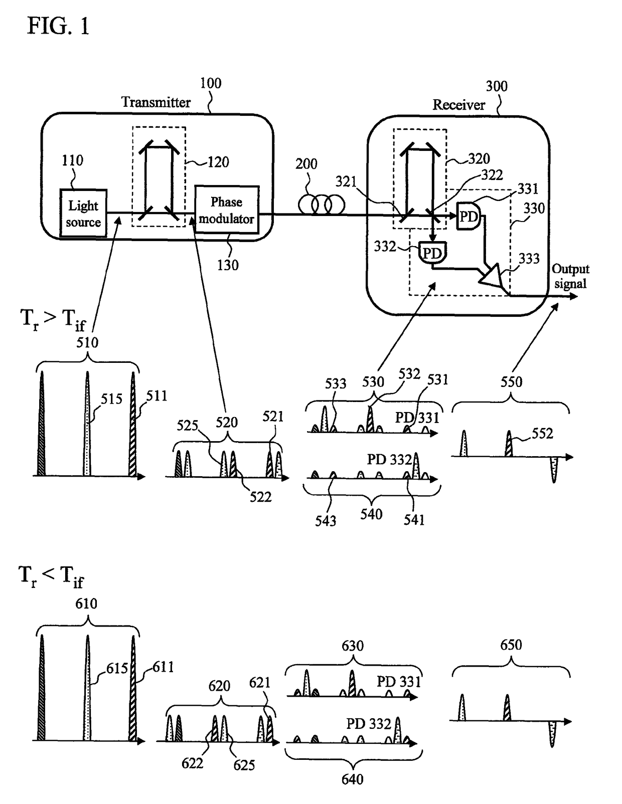
[0019]FIG. 1 is a block diagram showing an example of the optical transmitting and receiving system according to the present invention. The upper part of FIG. 1 is a system configuration diagram, and the lower part of FIG. 1 is a schematic waveform diagram showing how a train of pulses propagate. A train of optical pulses 510 outputted from a light source 110 are inputted to an asymmetric interferometer 120, where each of the pulses is split into two. The train of optical pulses 510 is thus converted into a train of dual pulses 520. For example, a pulse 511 is split into pulses 521 and 522. The distance between dual pulses (the distance between the pulses 521 and 522, for example) produced in the asymmetric interferometer 120 is longer than half the distance between pulses outputted from the light source 110 (the distance between the pulses 521 and 525, for example). As a result, the rear pulse of the dual pulses is closer to the pulse that is one period behind than to the front pul...

second embodiment

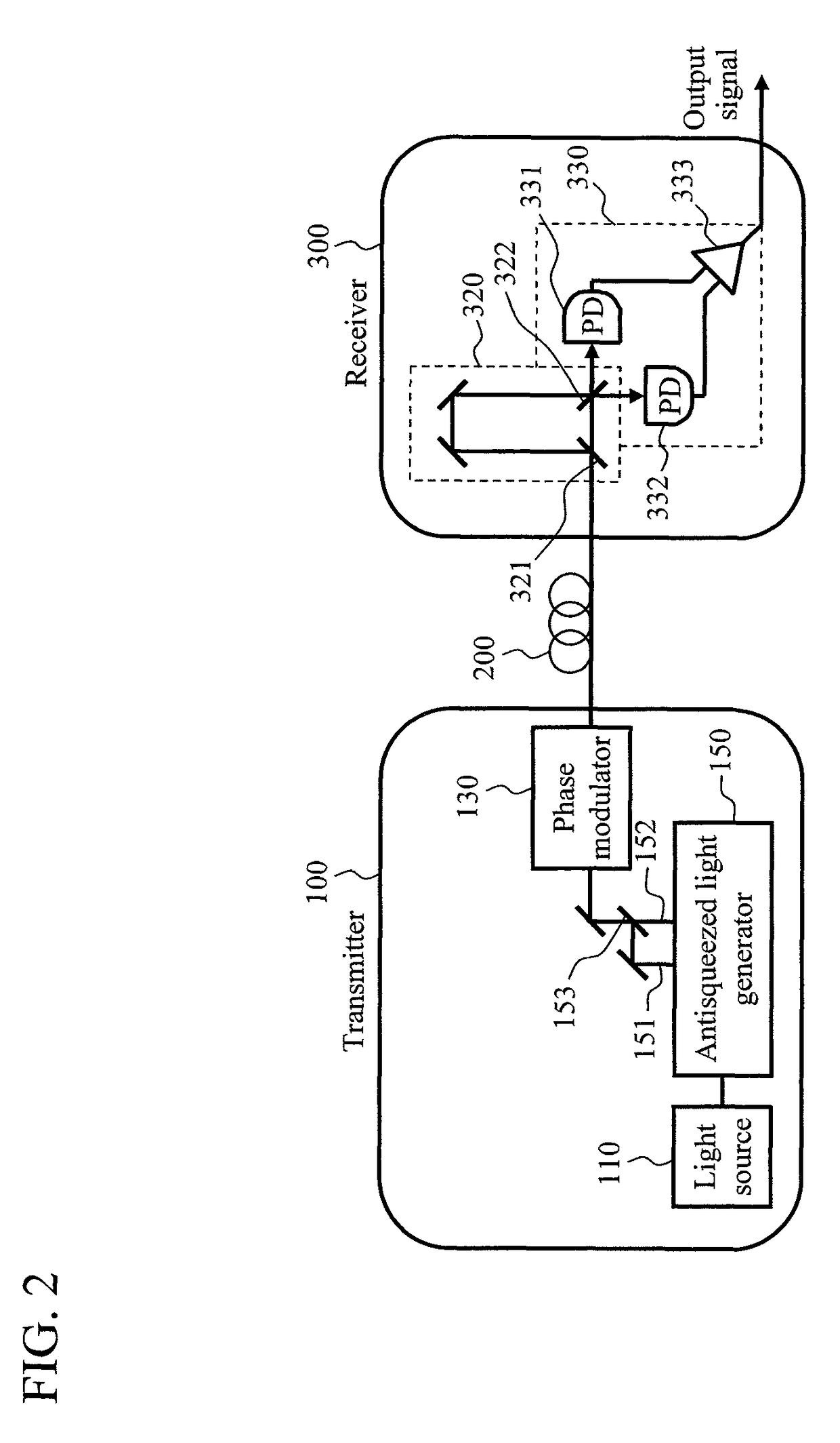
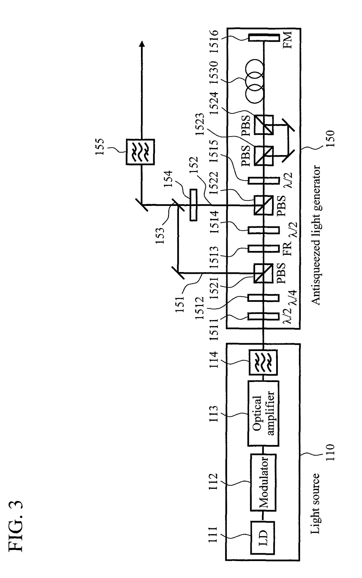
[0025]Consider the case where antisqueezed light (including squeezed light) is used as the low-coherence light. Antisqueezed light can be produced, for example, by using the Kerr effect of an optical fiber (JP Patent Publication (Kokai) No. 2006-191410). In the method using an optical fiber, when pump light enters the optical fiber, antisqueezed light and used pump light are obtained as the output. In the first embodiment, the asymmetric interferometer provided in the transmitter converts a single pulse into dual pulses. One of dual pulses may be antisqueezed light and the other one of the dual pulses may be used pump light. In the present invention, one of the dual pulses serves as reference light in the receiver, and the used pump light is suitable for reference light because the phase fluctuation of the used pump light is smaller than that of antisqueezed light.

[0026]FIG. 2 is a block diagram of the optical transmitting and receiving system according to this embodiment in which d...

third embodiment

[0032]The configuration of the receiver 300 shown in FIG. 1 is used in the case where signals are superimposed in the DPSK coding format, and includes a set of the asymmetric interferometer 320 and the balanced detector 330. When signals are superimposed in the DQPSK coding format, another set of asymmetric interferometer and balanced detector are required. An example of such a configuration is shown in FIG. 4. Asymmetric interferometers 320 and 325 are set with 90-degree different phase so that the balanced detectors 330 and 335 detect quadrature components different from each other. The outputs, which are the quadrature components different from each other, are combined in a signal synthesizer circuit 340 to get a final output signal. Two sets of asymmetric interferometer and balanced detector allow not only DQPSK-based signal coding but also multi-valued signal coding in which the number of multiple values is greater than that in DQPSK.

[0033]Similarly, in the embodiment shown in ...


PUM

PropertyMeasurementUnit
optical path lengthaaaaaaaaaa
phaseaaaaaaaaaa
delay timeaaaaaaaaaa

Abstract

Signals can be superimposed on optical phase even when low-coherency light is used, and a bit rate and a signal coding format similar to those used in ordinary optical communications can be used. A transmitter includes an asymmetric interferometer or an antisqueezed light generator to convert a train of single pulses into a train of dual pulses. A receiver also includes an asymmetric interferometer that provides the same delay time as that between the dual pulses. The receiver allows pulses originating in the same light source to interfere, so that signals can be superimposed on the phase even when a low-coherency light source is used. The delay time (optical path length difference) provided in the asymmetric interferometer is set to be longer than half the period of the pulses outputted from the optical pulse source. In the transmitter, two pulses are modulated as a unit, one of the two pulses being the rear pulse of a pair of dual pulses and the other pulse being the front pulse of the next pair of dual pulses. In the receiver, a balanced detector receives the modulated pulses, and the balanced detector only outputs interference pulses but does not output non-interference pulses.

Description

CLAIM OF PRIORITY[0001]The present application claims priority from Japanese Application JP 2007-158949 filed on Jun. 15, 2007, the content of which is hereby incorporated by reference into this application.BACKGROUND OF THE INVENTION[0002]1. Field of the Invention[0003]The present invention relates to an optical transmitting and receiving system, and more particularly to a signal superimposing method in optical communications. The optical transmitting and receiving system and the signal superimposing method are also effective in quantum communications.[0004]2. Background Art[0005]Secrecy requirement in communication has been and will be studied, but might never be fully satisfied. In the recent networking society, advances in cryptography have reasonably fulfilled such requirement. For example, the public key cryptosystem, which is widely used at present, is a software-based cryptograph based on the fact that it takes unrealistically long time to break a cryptogram even when a high...

Claims


Application Information

Patent Timeline
Patent Type & Authority Patents(United States)
IPC IPC(8): H04B10/12G02F1/01G02F2/00H04B10/516H04B10/548H04B10/58H04B10/61H04B10/85H04K1/02
CPCH04B10/505H04B10/5162H04B10/5561H04B10/677
Inventor TOMARU, TATSUYA
Owner HITACHI LTD
Why Eureka
Try Eureka