Semiconductor circuit
a technology of semiconductor and circuit, applied in the direction of pulse automatic control, pulse technique, electronic switching, etc., can solve the problems of imposing a limit on the ability to remove the error pulse with the phase difference, unintended on/off pulse, and complex total circuit, so as to prevent a malfunction and simple circuit configuration
- Summary
- Abstract
- Description
- Claims
- Application Information
AI Technical Summary
Benefits of technology
Problems solved by technology
Method used
Image
Examples
embodiment 1
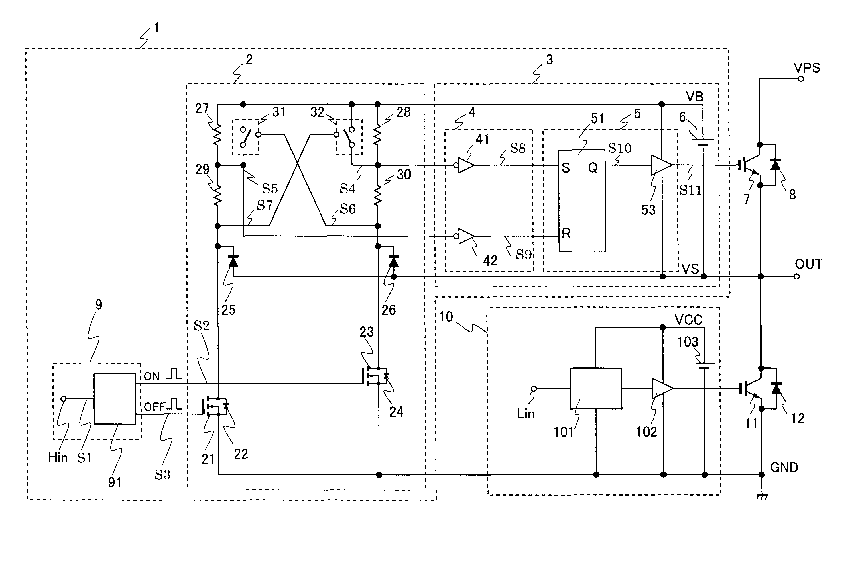
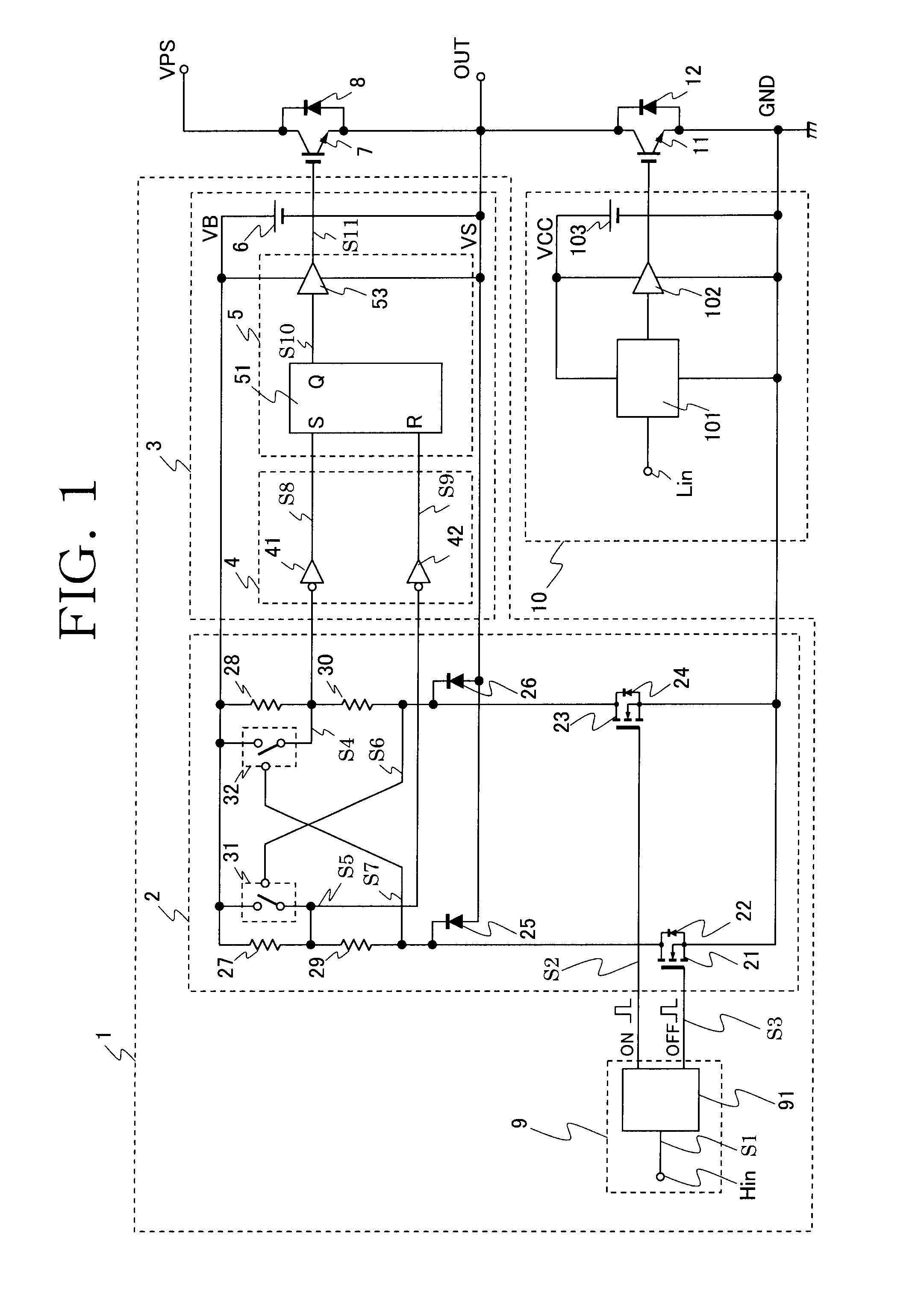
[0021]FIG. 1 shows an embodiment of a semiconductor circuit according to the present invention. Referring to FIG. 1, semiconductor switching devices 7 and 11, such as IGBTs, are connected in series between a main power source potential GND acting as a first potential or the common potential, and a main power source potential VPS of a high potential, which configures a half-bridge inverter circuit. In addition, flyback (or freewheeling) diodes 8 and 12 are connected in inverse parallel with the semiconductor switching devices 7 and 11, respectively, and a load, not shown, is to be connected to a junction—i.e., a terminal OUT—between the semiconductor switching devices 7 and 11.
[0022]Referring to FIG. 1, the semiconductor switching device 7 is called a high potential side switching device because it performs switching operation between a potential at the terminal OUT—the second potential—serving as a reference potential and the main power source VPS of the high potential.
[0023]Further...
embodiment 2
[0058]FIG. 3 shows a semiconductor circuit according to Embodiment 2 of the present invention. Components and signals that are the same as those in Embodiment 1 hereinafter bear the same reference numerals, and their description is not provided.
[0059]In the present embodiment, analog switches 33 and 34 are employed as a specific example of the switch serving as the short circuit device described in Embodiment 1. This enables speedy and accurate control of the short circuit and open circuit.
embodiment 3
[0060]FIG. 4 shows a semiconductor circuit according to Embodiment 3 of the present invention. In the present embodiment, Pch MOS transistors 35 and 36 are used as a specific example of the switch serving as the short circuit device described in Embodiment 1. The use of the Pch MOS transistors configurable by a standard CMOS process enables prevention of an increase in chip size of the semiconductor circuit. Further, since the threshold value of the Pch MOS transistor is about one volt in a typical example, it is possible to easily implement an embodiment circuit, described to be preferable in Embodiment 1, in which the logic threshold values of the short circuit devices are set to be smaller than those of the first and second inverse logic devices 41 and 42.
PUM
 Abstract
Description
Claims
Application Information
 - R&D
- Intellectual Property
- Life Sciences
- Materials
- Tech Scout
- Unparalleled Data Quality
- Higher Quality Content
- 60% Fewer Hallucinations
Browse by: Latest US Patents, China's latest patents, Technical Efficacy Thesaurus, Application Domain, Technology Topic, Popular Technical Reports.
© 2025 PatSnap. All rights reserved.Legal|Privacy policy|Modern Slavery Act Transparency Statement|Sitemap|About US| Contact US: help@patsnap.com


