Process for repairing a component comprising a directional microstructure by setting a temperature gradient during the laser heat action, and a component produced by such a process

a technology of laser heat action and component, which is applied in the direction of manufacturing tools, turbines, and so on, can solve the problems of material properties that are worse than those of the surrounding, and the material does not have a single crystal or directionally solidified structur

Inactive Publication Date: 2012-03-27
SIEMENS AG
View PDF52 Cites 21 Cited by
  • Summary
  • Abstract
  • Description
  • Claims
  • Application Information

AI Technical Summary

Benefits of technology

[0019]In the soldering process, only the solder but not the base material is melted and allowed to solidify again, with the solder forming a join with the base material, so that the repair process according to the invention can be used even in structurally bearing regions of the component without adversely affecting the good materials properties of the base material. Epitaxial growth and solidification of the solder, i.e. growth in which the crystalline orientation of the solder during solidification is determined by that of the substrate, i.e. the base material, can be achieved by means of the temperature gradient. Therefore, the temperature gradient allows the formation of a single-crystal solder region or another directional microstructure in the soldered solder with materials properties that are similarly improved compared to an undirectional microstructure. The directional growth takes place in the direction of the temperature gradient, i.e. in the direction from the lower temperature to the higher temperature. On account of the directional growth and the resulting directional microstructure, the soldered solder had similarly good materials properties to the base material of the component.
[0020]It is preferable for the temperature gradient in the repair process according to the invention to be generated in such a manner that it extends in the direction of orientation of the directional microstructure of the base material of the component. It is in this way possible to achieve a directional growth of the solidifying solder in the direction of orientation of the directional microstructure of the base material.
[0021]In an advantageous refinement of the process according to the invention, the solder includes a first constituent with a melting temperature, which is lower, preferably significantly lower, than the melting temperature of the base material of the component and a second constituent with a high strength and a melting temperature that is above the melting temperature of the first constituent but below the melting temperature up to the melting temperature of the base material. In this refinement of the process, the solder is applied in such a manner in the region of the location that is to be soldered that the proportion of the first constituent in the solder is higher in the local vicinity of the base material than in a region further away from the base material. In this configuration of the process, the first constituent with the low melting temperature serves to produce the join between the solder and the base material, while the constituent with the high melting temperature is responsible for the durability (strength) of the soldered solder. As a result of the solder having a higher proportion of the first constituent in the region of the base material, it is possible to produce a good join between the soldered solder and the base material. On the other hand, in regions which are further away from the base material, in relative terms more second constituent, i.e. more of the constituent with the higher durability, is present, with the result that those regions of the soldered location that, during subsequent operation of the component, are subject to higher stresses have a higher durability.

Problems solved by technology

However, after the soldering, in the procedure which has been customary hitherto, the solder material does not have a single-crystal or directionally solidified structure.
However, an unordered structure brings with it materials properties that are worse than those of a directional microstructure, in particular in the high-temperature range, with the result that the soldered location then has materials properties that are worse than those of the surrounding base material.

Method used


Image

  • Process for repairing a component comprising a directional microstructure by setting a temperature gradient during the laser heat action, and a component produced by such a process
  • Process for repairing a component comprising a directional microstructure by setting a temperature gradient during the laser heat action, and a component produced by such a process
  • Process for repairing a component comprising a directional microstructure by setting a temperature gradient during the laser heat action, and a component produced by such a process

Examples


Embodiment Construction

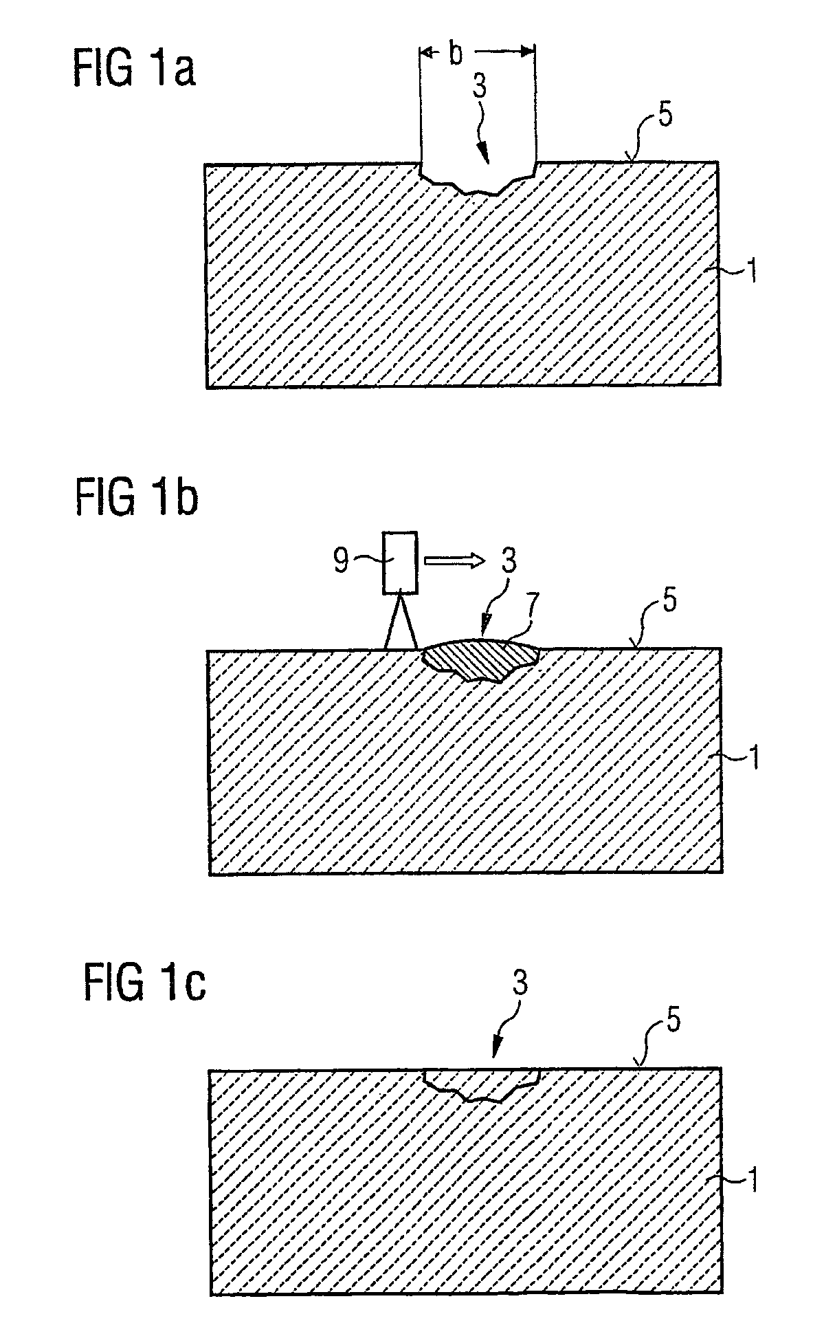
[0031]FIG. 1a provides a schematic view of a damaged component 1.

[0032]The base material of the component 1 comprises an alloy, preferably based on nickel, and has a directional microstructure, which in the figures is indicated by short diagonal dashes. The damage 3 to the component 1 is located in the region of the surface 5 and is illustrated as an indentation in the figure.

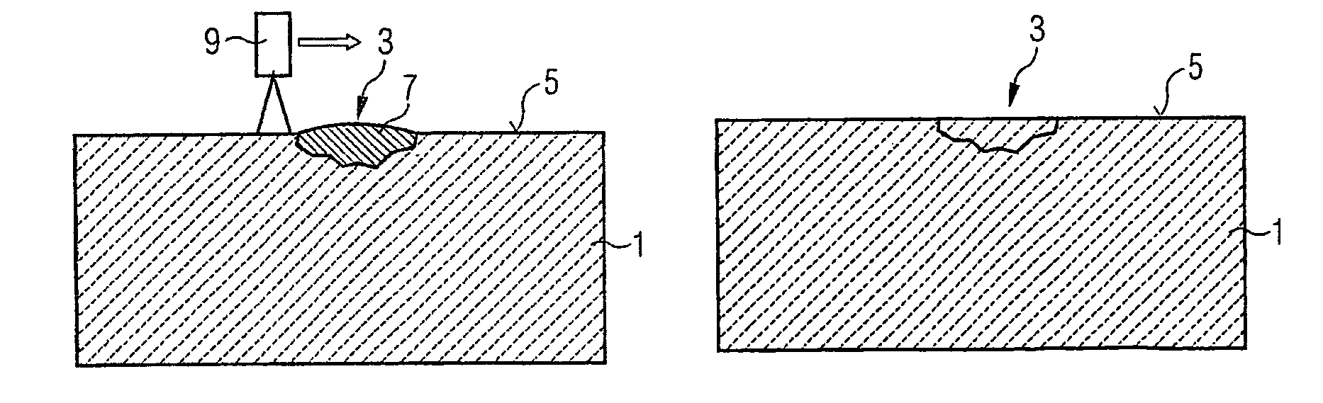
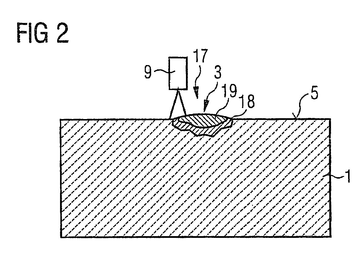
[0033]To repair the damaged component 1, a solder 7, which in the present exemplary embodiment is preferably in powder form, is applied to the precleaned, damaged location 3 and is then soldered to the base material of the component 1 by means of the action of heat (FIG. 1b). It is preferable for all of the solder 7 required to be introduced into the preferably precleaned, damaged location 3, if appropriate in a small excess, and in particular for it not to be supplied in steps during the fusing operation.

[0034]Prior to fusing, it is preferable for the solder 7 to be pressed into the damaged location 3. This ha...


PUM

PropertyMeasurementUnit
melting temperatureaaaaaaaaaa

Abstract

In one aspect, a repair method for repairing components comprising a base material with a directed microstructure is provided. The repair is performed in such a way that the repaired location correspondingly has a directed microstructure like the surrounding base material. A solder is applied in the region of a location to be repaired and is soldered to the component via heat exposure, a temperature gradient, i.e., for instance a temperature variation from a higher temperature to a lower temperature, is thereby produced in the region of the location to be repaired.

Description

CROSS REFERENCE TO RELATED APPLICATIONS[0001]This application is the US National Stage of International Application No. PCT / EP2005 / 008038, filed Jul. 22, 2005 and claims the benefit thereof. The International Application is incorporated by reference herein in its entirety.FIELD OF INVENTION[0002]The present invention relates to a process for repairing a component which comprises a base material with a directional microstructure and to a component according to the independent claims.BACKGROUND OF INVENTION[0003]Nowadays, turbine components are often made from materials with a directional microstructure. In this context, materials with a directional microstructure are to be understood as meaning in particular single-crystal materials and materials which have a grain structure wherein the grains extend in a common preferential direction. By way of example, the grains may have a larger dimension in a certain preferential direction than in the other directions. Components with a grain st...

Claims


Application Information

Patent Timeline
Patent Type & Authority Patents(United States)
IPC IPC(8): B23K26/34B23K31/02
CPCB23K1/0018B23K1/002B23K1/0056B23P6/007B23K2201/001B23K2101/001
Inventor OTT, MICHAELPAUL, UWESINGER, ROBERTVOLEK, ANDREAS
Owner SIEMENS AG
Why Eureka
Try Eureka