

Hydrogen passivation shut down system for a fuel cell power plant
a technology of hydrogen passivation and shut down system, which is applied in the direction of cell components, cell component details, electrochemical generators, etc., can solve the problems of inability to meet the requirements of the power plant,
- Summary
- Abstract
- Description
- Claims
- Application Information
AI Technical Summary
Benefits of technology
Problems solved by technology
Method used
Image

Examples
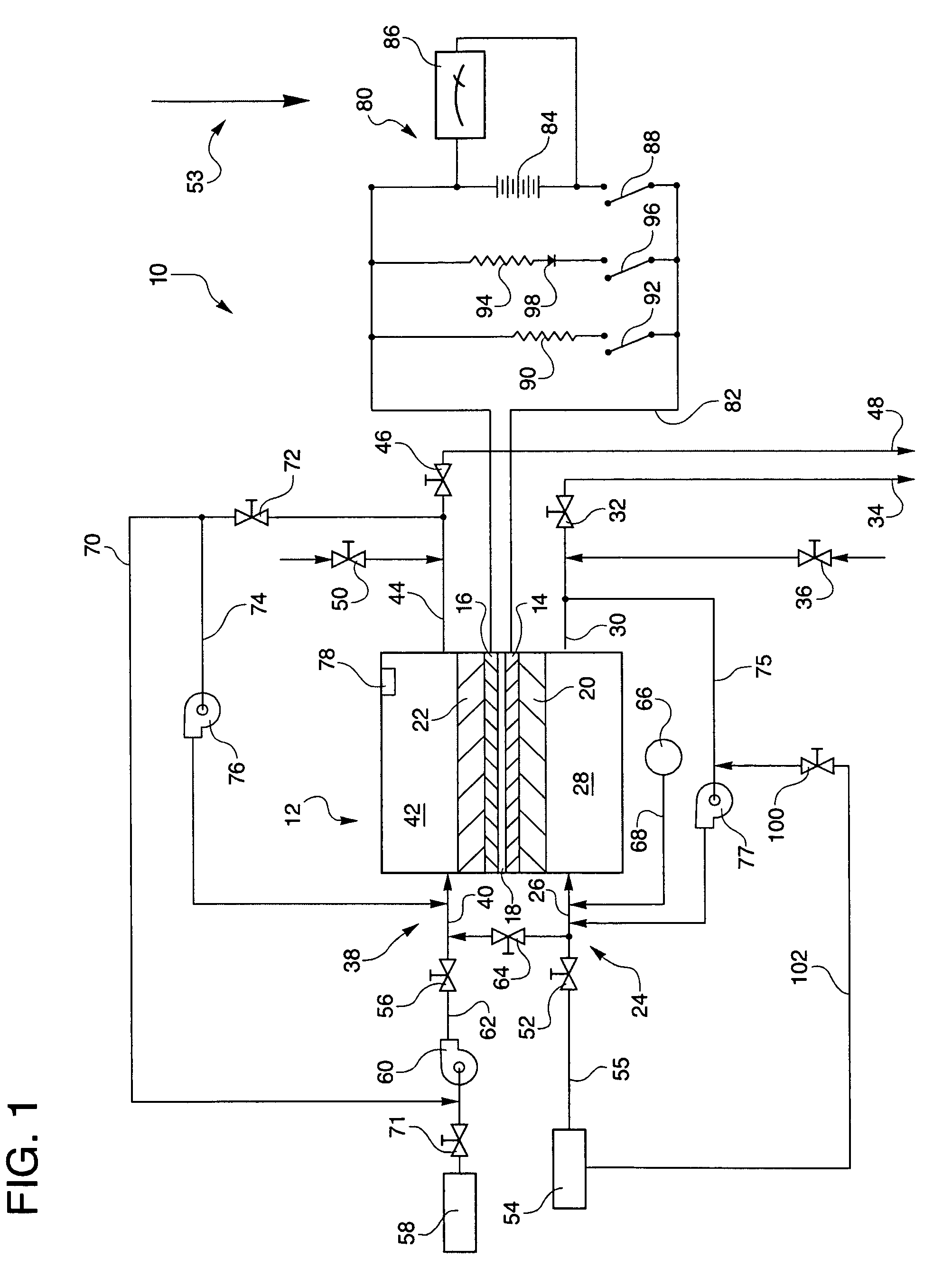
first embodiment
[0029]Referring to the drawings in detail, a hydrogen passivation shut down system for a fuel cell power plant is shown in FIG. 1, and is generally designated by the reference numeral 10. The system 10 includes at least one fuel cell, such as a fuel cell 12 having an anode catalyst 14 (which may also be referred to herein as an anode electrode), a cathode catalyst 16 (which may also be referred to as a cathode electrode), and an electrolyte 18 disposed between the anode and cathode. The electrolyte 18 may be in the form of a proton exchange membrane (PEM) of the type described in U.S. Pat. No. 6,024,848, or the electrolyte may be held within a ceramic matrix, such as is typically found in acid aqueous electrolyte fuel cells, such as phosphoric acid electrolyte fuel cells.
[0030]The anode catalyst 14 may be supported on an anode substrate layer 20, and the cathode electrode 16 may be supported on a cathode substrate layer 22. The system 10 also includes an anode flow path 24 in fluid ...
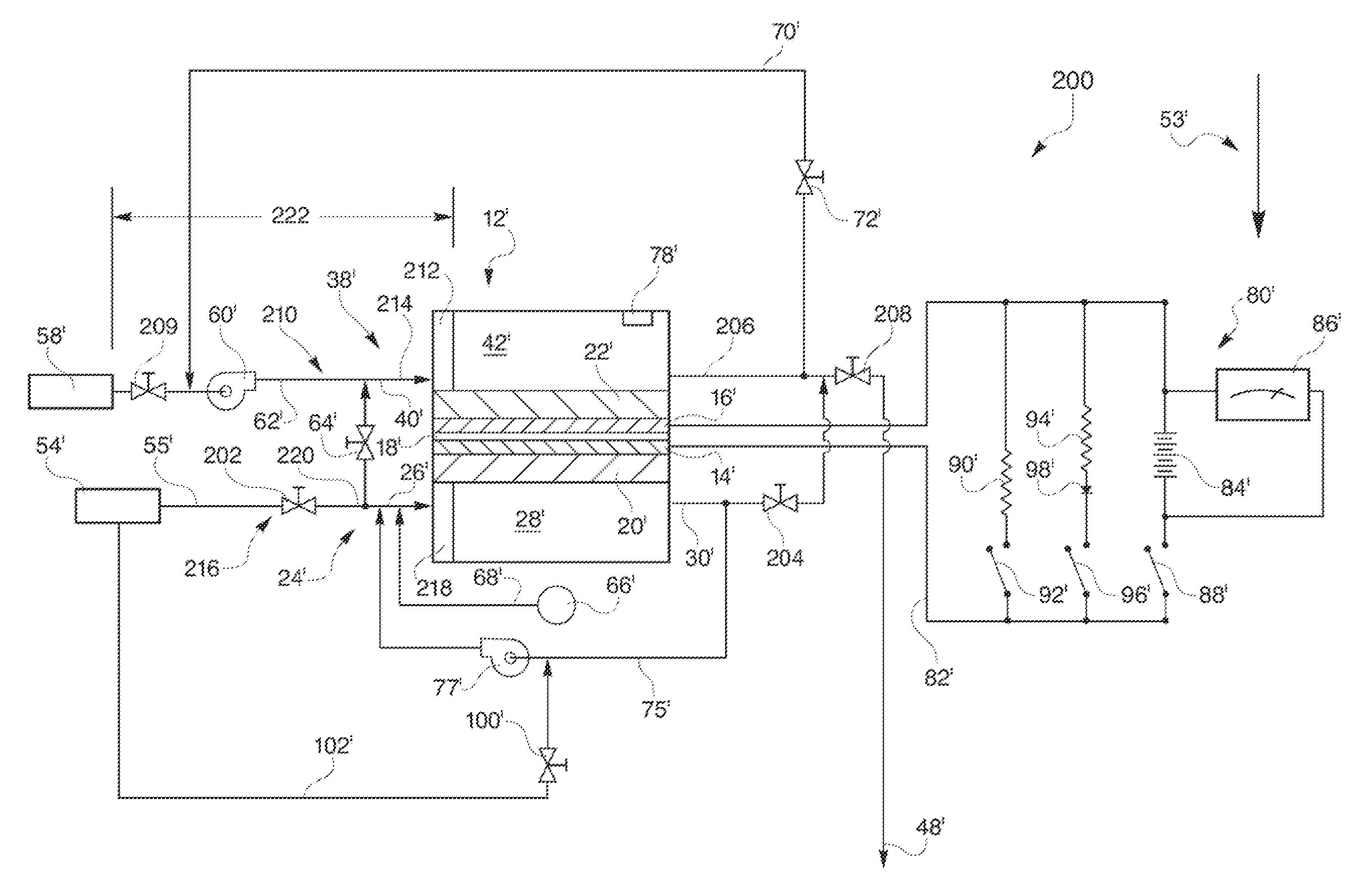
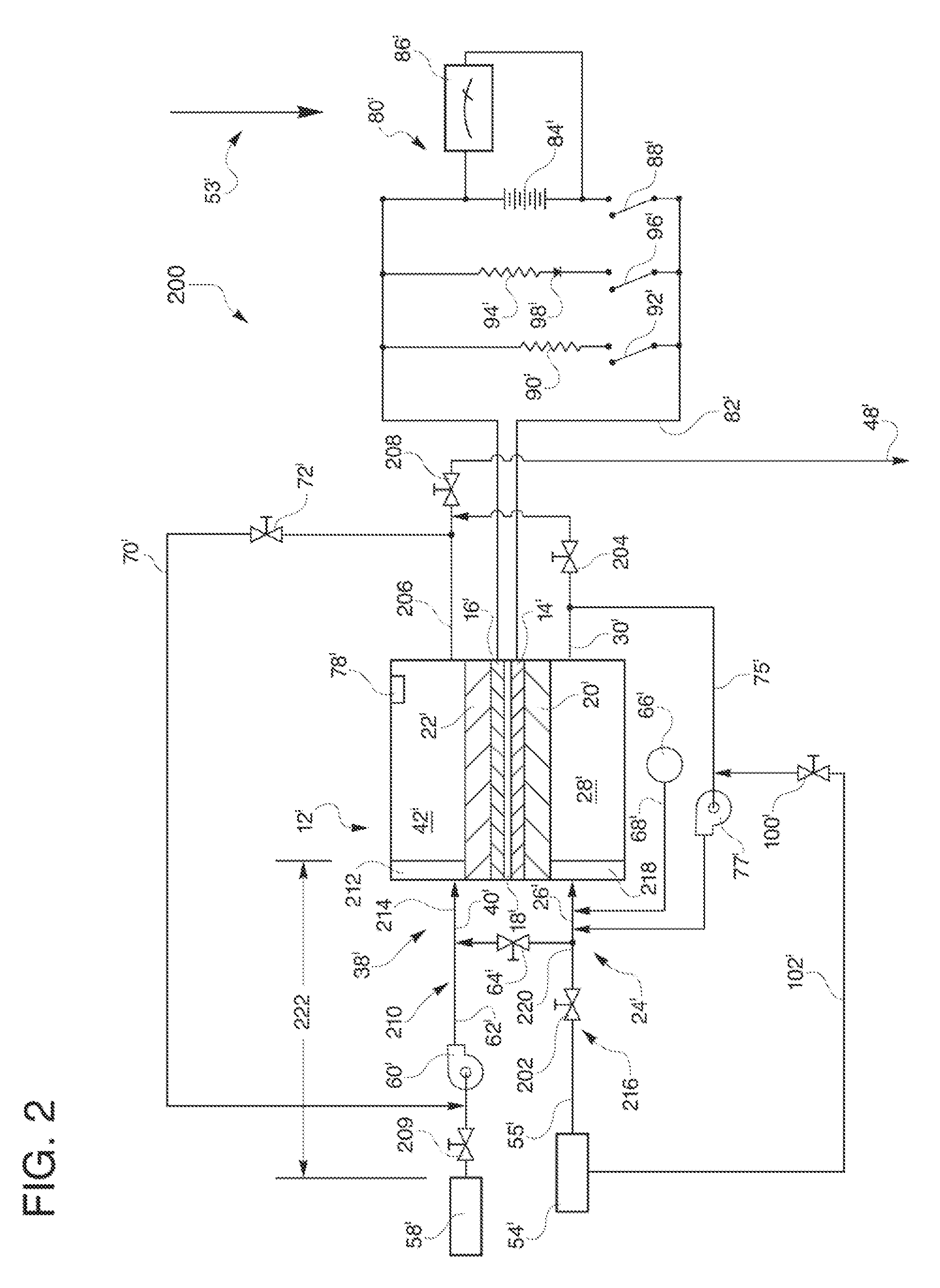
embodiment 200
[0057]The controlled-oxidant flow embodiment 200 also includes an oxidant inlet 210 for directing the oxidant from the controlled-oxidant flow inlet device 209 to a cathode flow field 42′. The oxidant inlet 210 includes a portion of the oxidant feed line 62′ and an oxidant manifold 212 between the controlled-oxidant flow inlet device 209 and the cathode flow field 42′. The oxidant inlet 210 defines an oxidant buffer void 214 extending between and in fluid communication with the oxidant feed line 62′ and the cathode flow field 42′ through which the oxidant passes.
[0058]A hydrogen inlet 216 extends between and in fluid communication with the non-leaking hydrogen inlet valve 202 and an anode flow field 28′ and includes a portion of the fuel feed line 55′ down stream from the non-leaking hydrogen inlet valve 202 and a fuel manifold 218. The hydrogen inlet 216 defines a hydrogen void 220 extending between and in fluid communication with the non-leaking hydrogen inlet valve 202 and the an...
PUM
| Property | Measurement | Unit |
|---|---|---|
| pressure | aaaaa | aaaaa |
| electrical current | aaaaa | aaaaa |
| volume | aaaaa | aaaaa |
Abstract
Description
Claims
Application Information